Allan Holdsworth Harness Inductor Experiment(s)
Created 12/3/23
By Paul J. Marossy
I wanted to get an idea of how much the inductors in the Allan Holdsworth Harness may be affected by the way they are mounted on the metal baseplate (assuming it's
aluminum for now), the bolts fastening them to the baseplate and the large washers on the top of the plastic bobbin. Below are details of some simple tests that I did while debating whether to order an actual 1mH inductor to do a more accurate test. My findings were very interesting nonetheless. Read to the end to see the progression from my simplistic experiment all the way to my conclusions. I guess the next step now will be to get proper 1mH air core inductors and perform the experiment again. In addition
to this inductance experiment I will try to determine how this affects frequency response. With the LTSpice simulations I did, I suspect it will be most apparent in the frequencies above 2kHz or so. I am also interested in seeing how close is my estimate of 20% more inductance due to the metal bits. I'll update this webpage when I get all that done in the near future. Update 12/10/23:
While I was waiting for my proper 1mH crossover coils to arrive I made two quick hand wound inductors to see how it might differ from my initial test. The results were surprising! This coil doesn't quite match the specs of the type of chokes I believe Allan used but it's much closer in terms of inductance. Even though I have a fairly good idea of what the outcome will be, it will still be interesting to see how a proper perfectly manufactured 1mH inductor will compare to my two previous tests. Based on these tests I'm guessing the apparent inductance will be considerably more than my initial estimate of 20%. So, we can see that another factor in this simple yet surprisingly complex circuit is that the mutual inductance may also have some effect on the sound. In Allan's circuit the "chokes" are in rather close proximity to each other, which in ordinary circumstances would create crosstalk and it does here also. My testing has confirmed that the baseplate does not negate that effect. I am not sure how this affects things in the overall picture. It may just contribute more to the losses of the inductors, and/or it may also actually impart something to the sound that can not be achieved any other way.
In conclusion, I don't know that I can really make any concrete conclusions but I found this exercise to be very interesting. I learned a few things I did not know before, and with so many variables, it is still somewhat mysterious as to what actually happens inside these boxes that Allan designed and built. I can not determine that without actually having one in hand to test and measure. In any case, this device may be another legitimate Holdsworth secret sauce kind of thing. All things considered, I think The Harness is definitely responsible for some of Allan's best "tones", such as the ones on the Secrets album. Who knew The Harness had so many secrets?! I think I know enough now to build a functional unit, which I may do just for kicks. I will replicate the component layout that Allan used and get all the proper parts so I can replicate it as closely as possible.
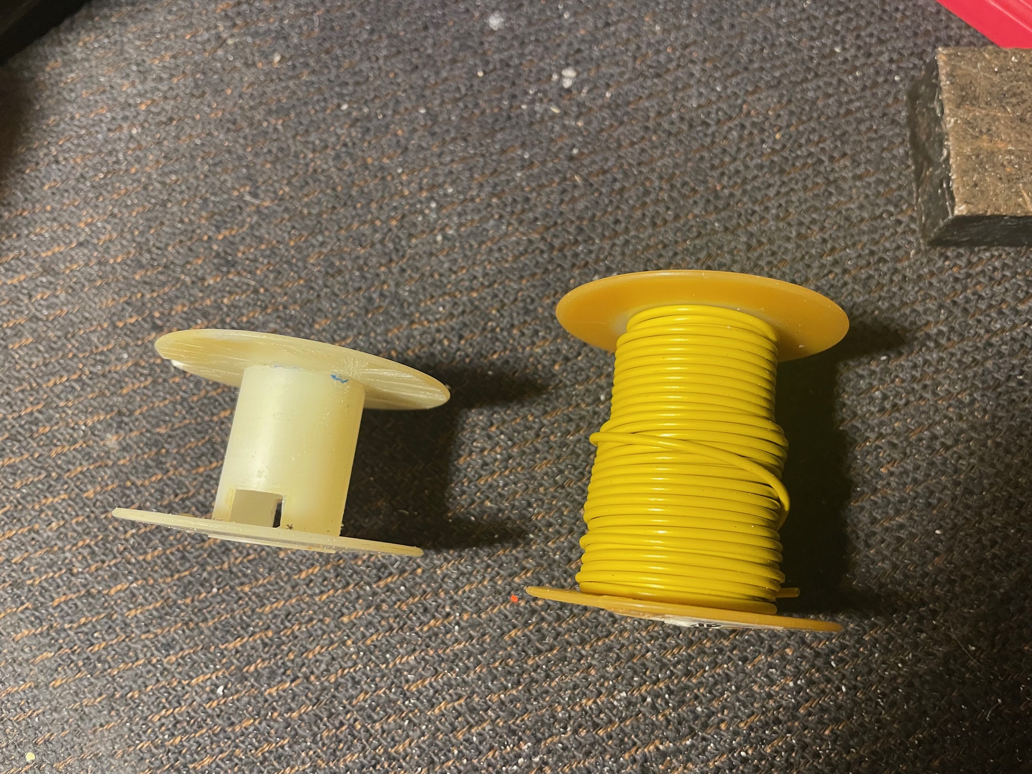
First thing I had to do was to create a bobbin that was 1" tall. I had some 2" tall spools of 18 gage wire left over from my first
tube amp project a long time ago. I chopped one down and made it 1" tall in only a few minutes.
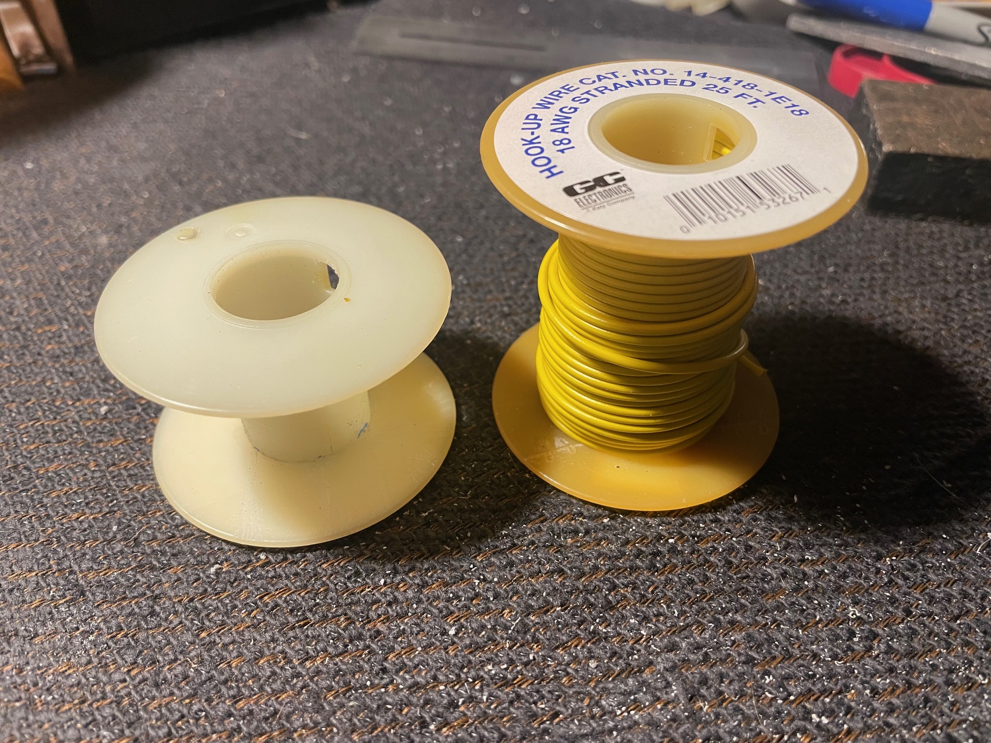
This wire makes for a terrible air core inductor but this is just an experiment. The dimensions of the 2" tall bobbin appear to be
otherwise identical to what Allan used in the Harness. (I am not 100% sure if the ones in Allan's units are 1" or 3/4" tall but, they seem more like 3/4")
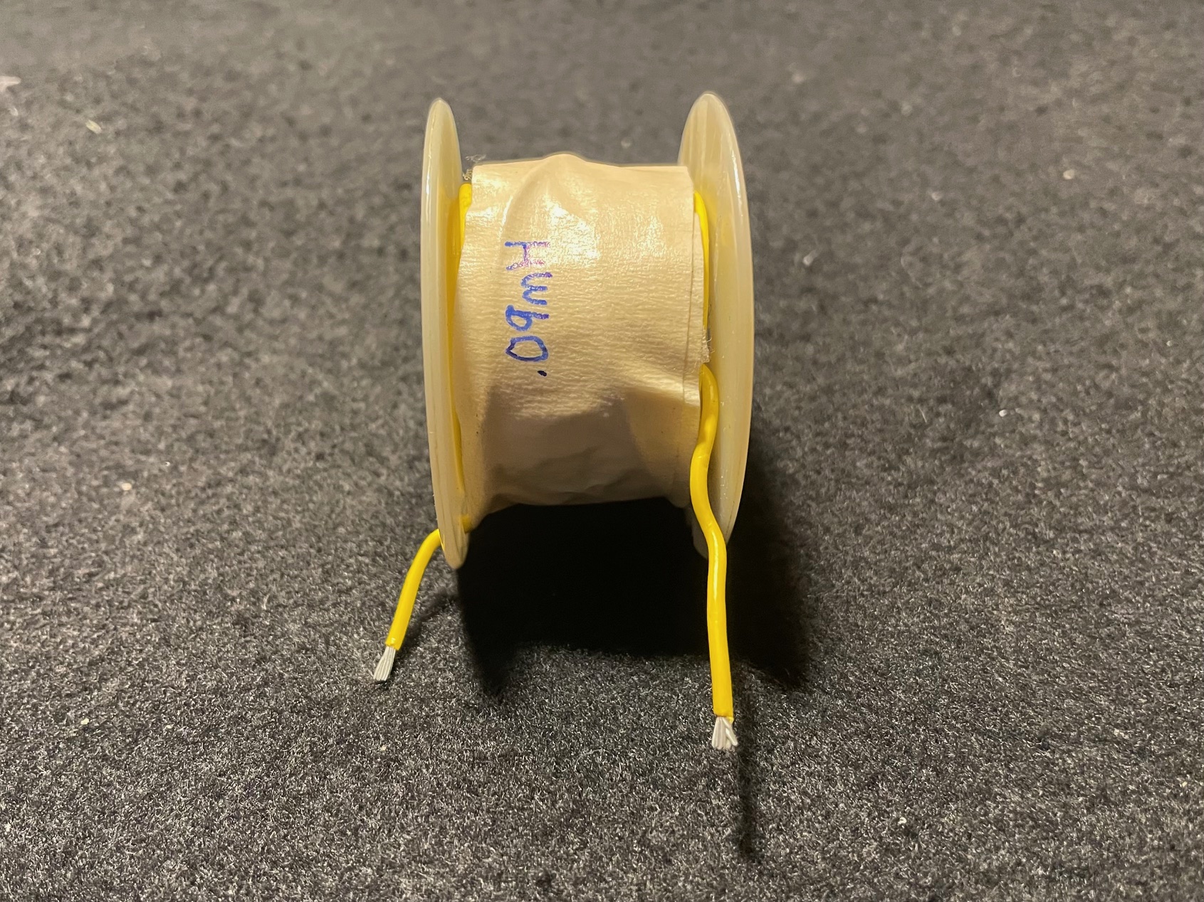
Here I have wrapped the bobbin with all the wire I had left on that spool.
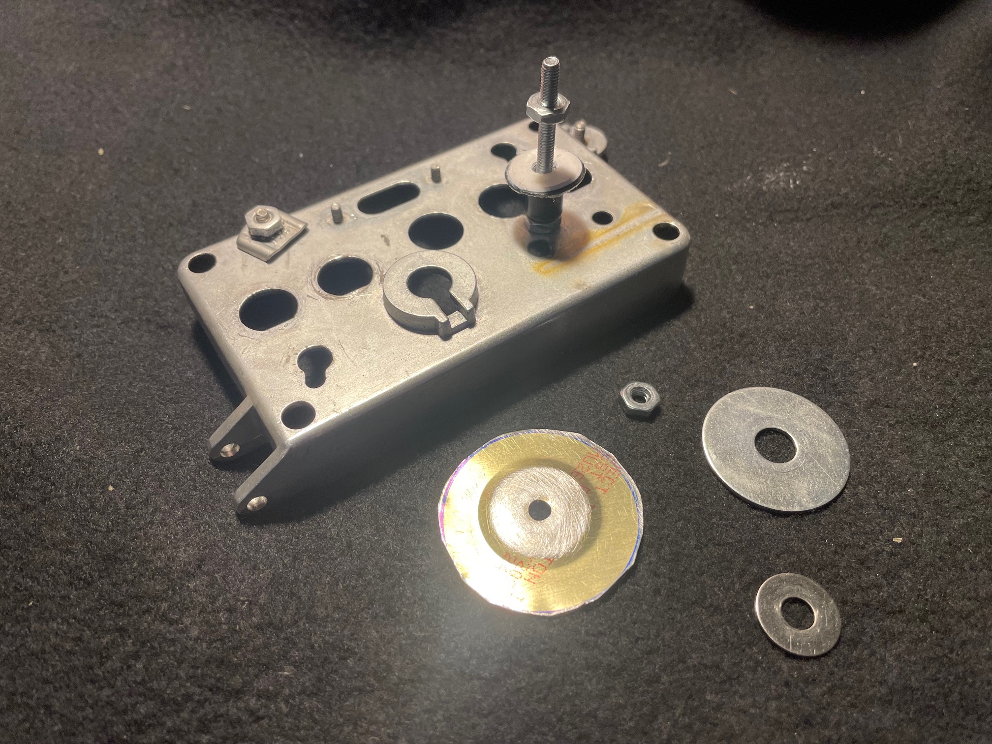
Here are the other parts used: An aluminum piece from a junked oscilloscope which will serve as a baseplate, a 2" long screw, a 1-1/4" diameter flat washer
and a 1-1/2" "washer" made from a jar lid cut down to size with some metal shears.
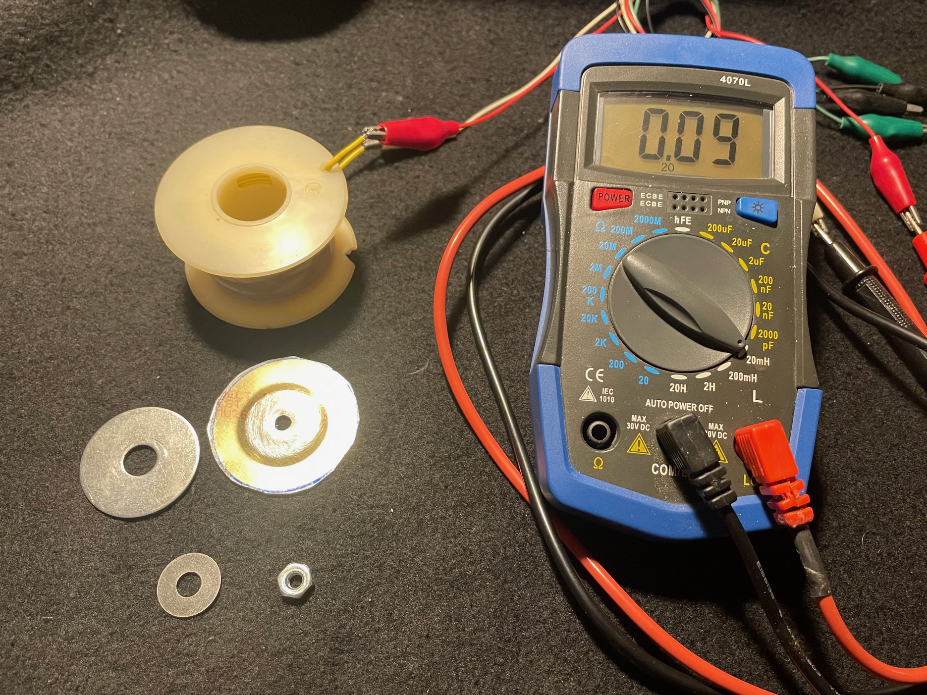
The "inductor" all by itself measures 0.09 millihenries. Not surprising considering how inefficient it is with that thick insulation and the fact
that it's 18 AWG stranded wire.
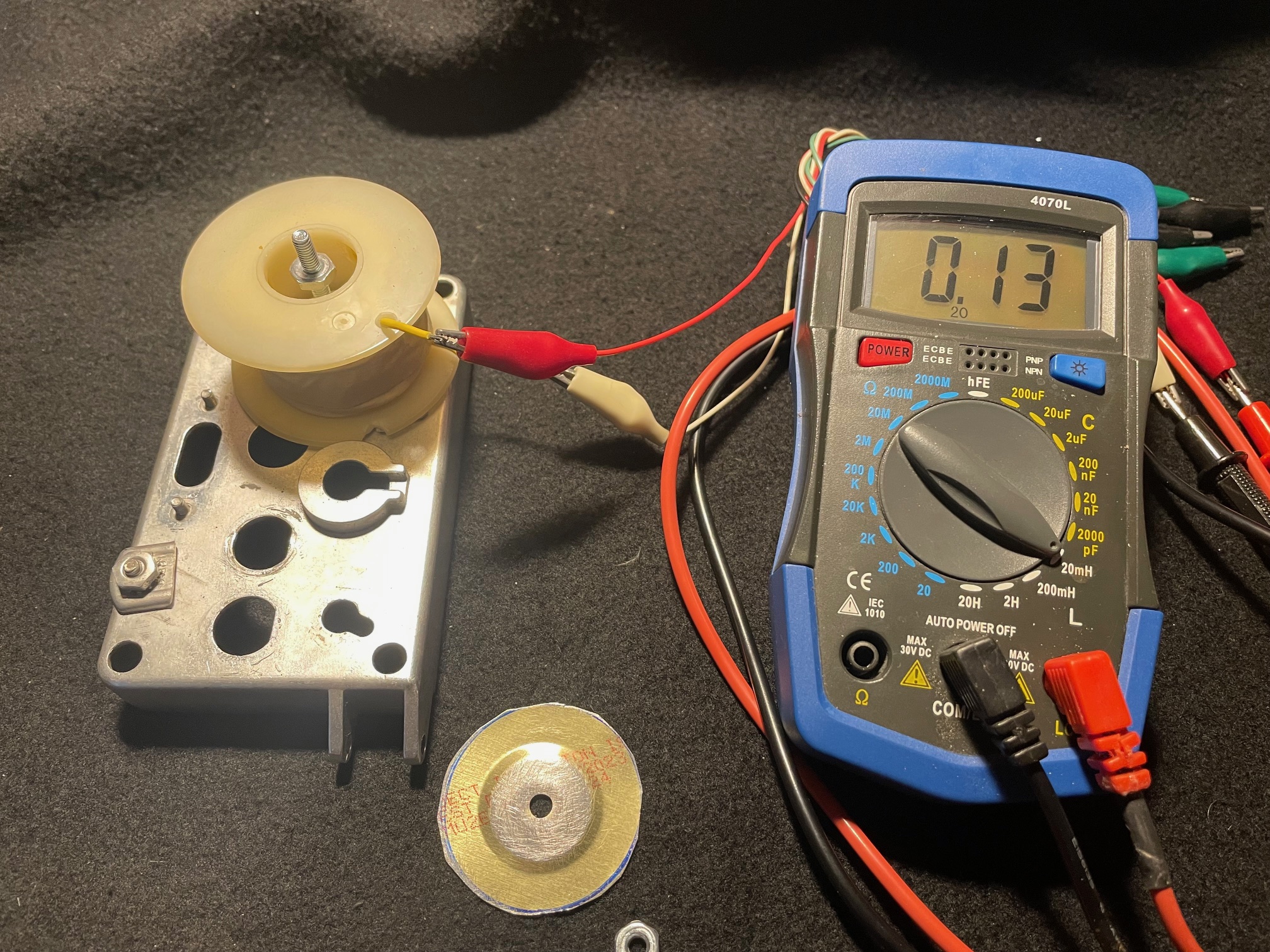
As soon as I put the "inductor" on the aluminum base (with screw in center of bobbin) the apparent inductance went up to 0.13 millihenries. That's
an increase of 44%. I'm sure this is because the amount of inductance is very small - roughly 1/10 of the nominal 1mH inductors believed to be used in The Harness. I
suspect that even with the 1mH inductor the affect will still be fairly significant.
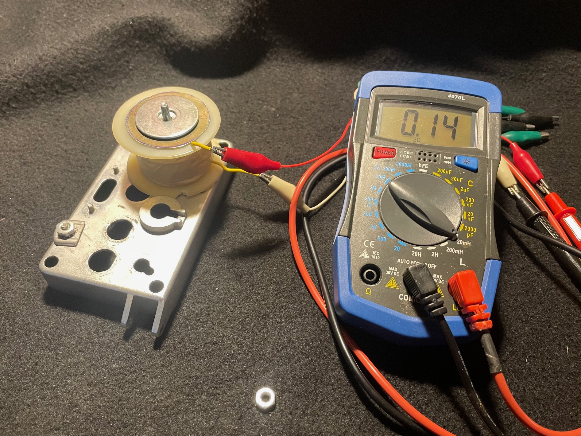
As soon as I put either type of washer on the top of the "inductor" the apparent inductance went up to 0.14 millihenries.
That makes the overall increase 55%.
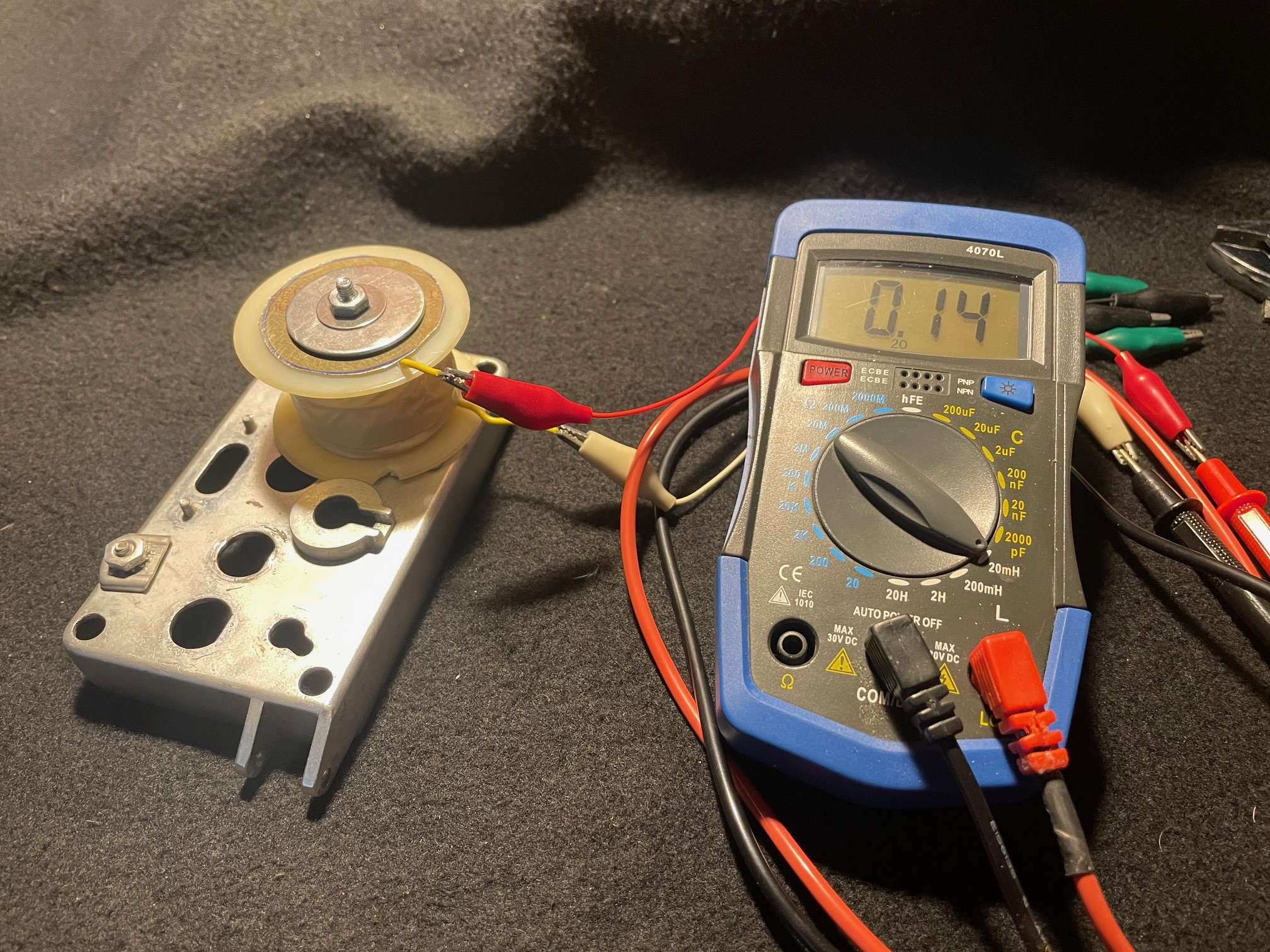
The addition of the nut on top did not affect anything.
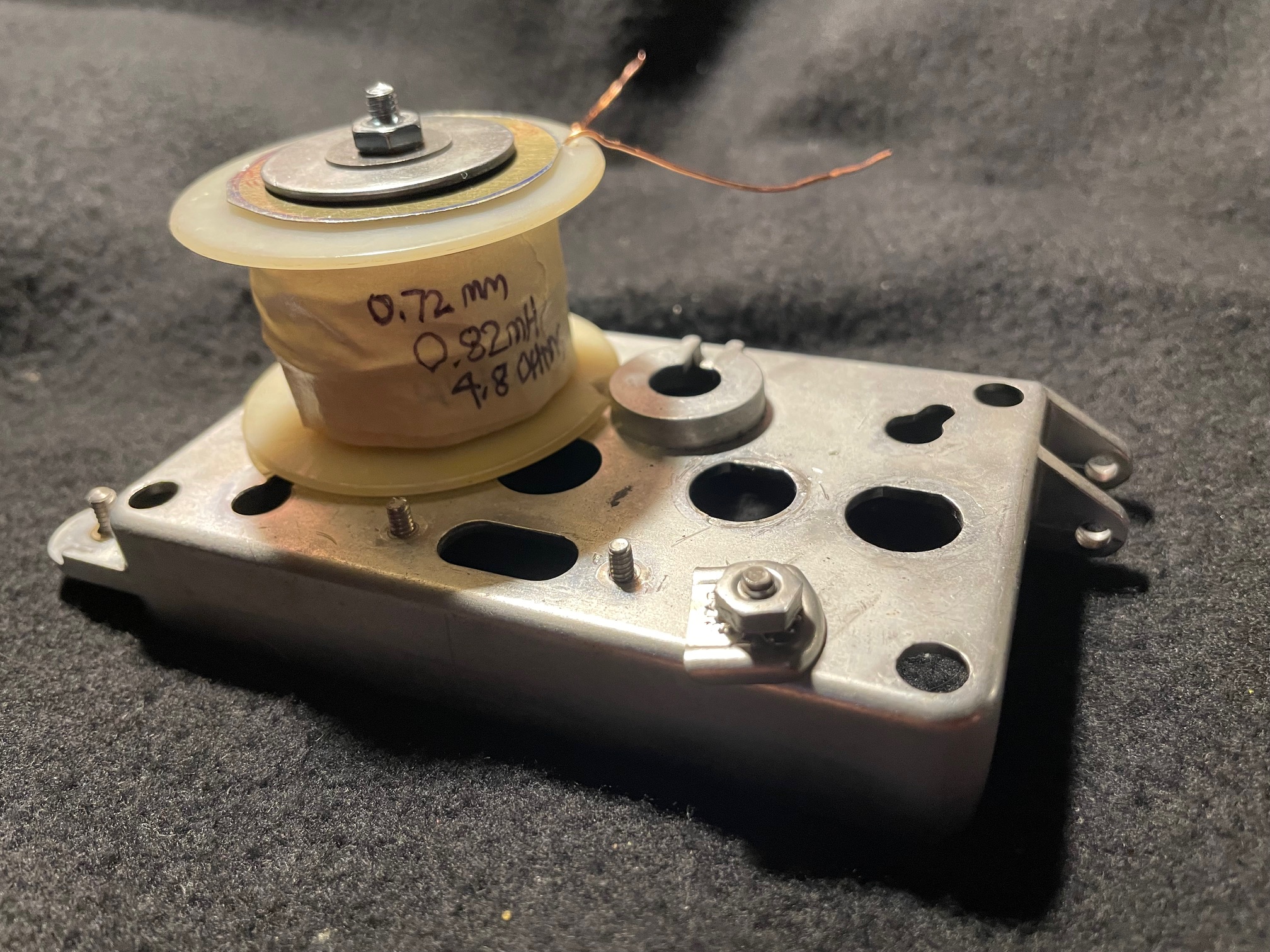
This coil was wound using approx. 22 AWG enameled wire. I don't know how many turns it ended up being but it measured 0.82mH when by itself.
As soon as I put it on the aluminum baseplate (with screw in center of the bobbin) the apparent inductance went up to 1.26mh. With the addition of the nut and
washers it settled at 1.36mH. That adds up to an increase of 65%! Far more than I was expecting to see.
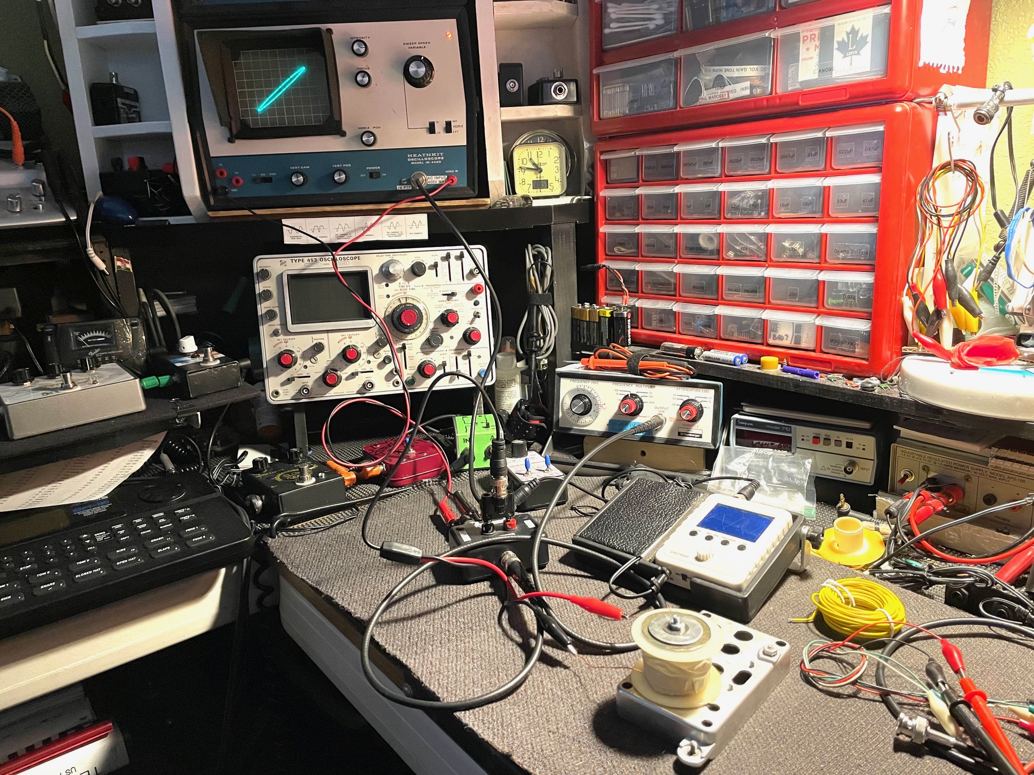
While I was at it, I thought I'd figure out what the resonant frequency of my coil was using my DIY curve tracer. It occurs at
about 65Hz, which is not too far off from the resonant frequency of a 12" guitar speaker, which can be anywhere between 55Hz & 75Hz. A "broken in"
speaker will typically have a resonant frequency of 60-65Hz, while a new one will often be at about 75Hz. With two inductors in series the resonant
frequency went down to about 50Hz.
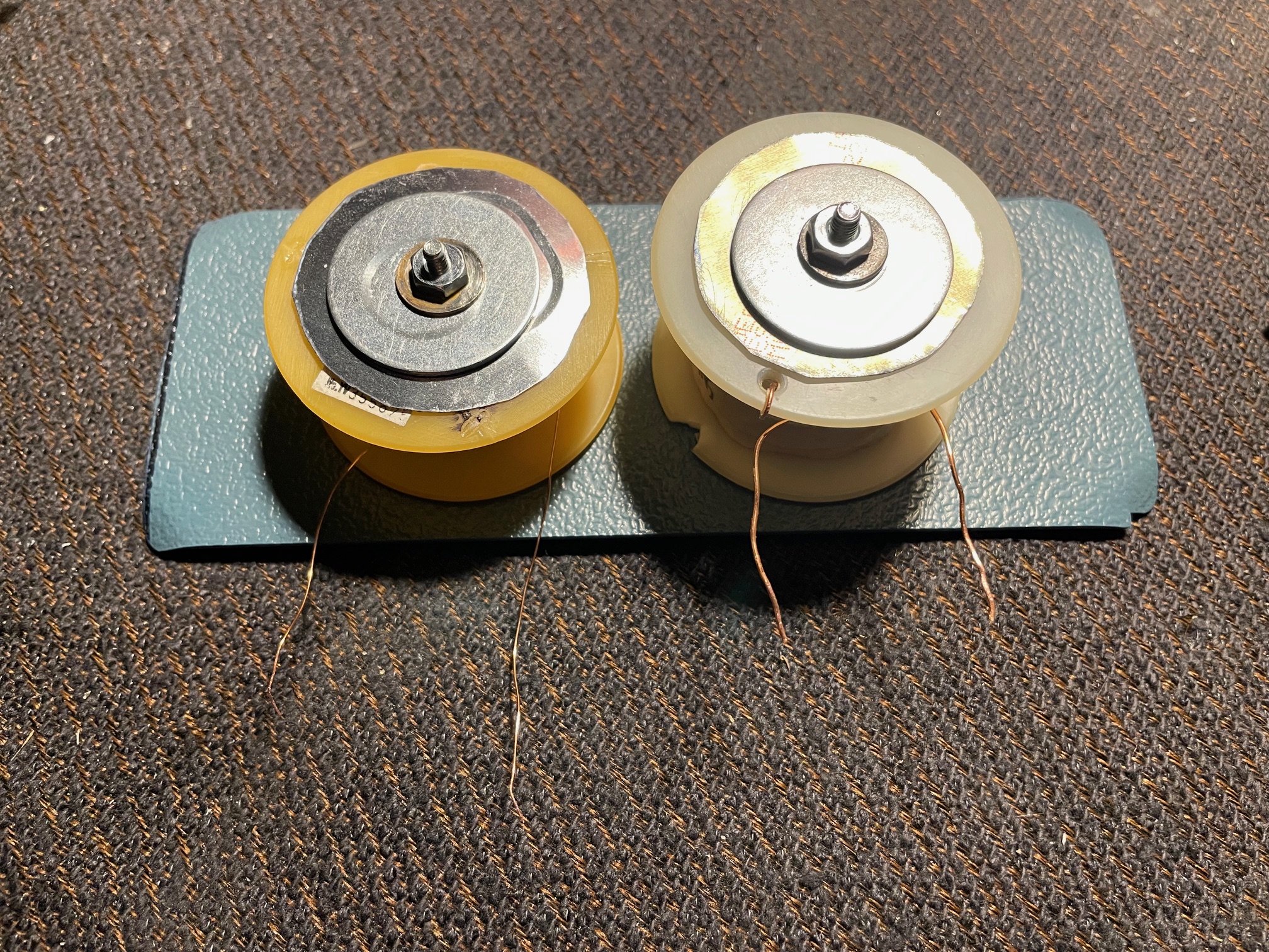
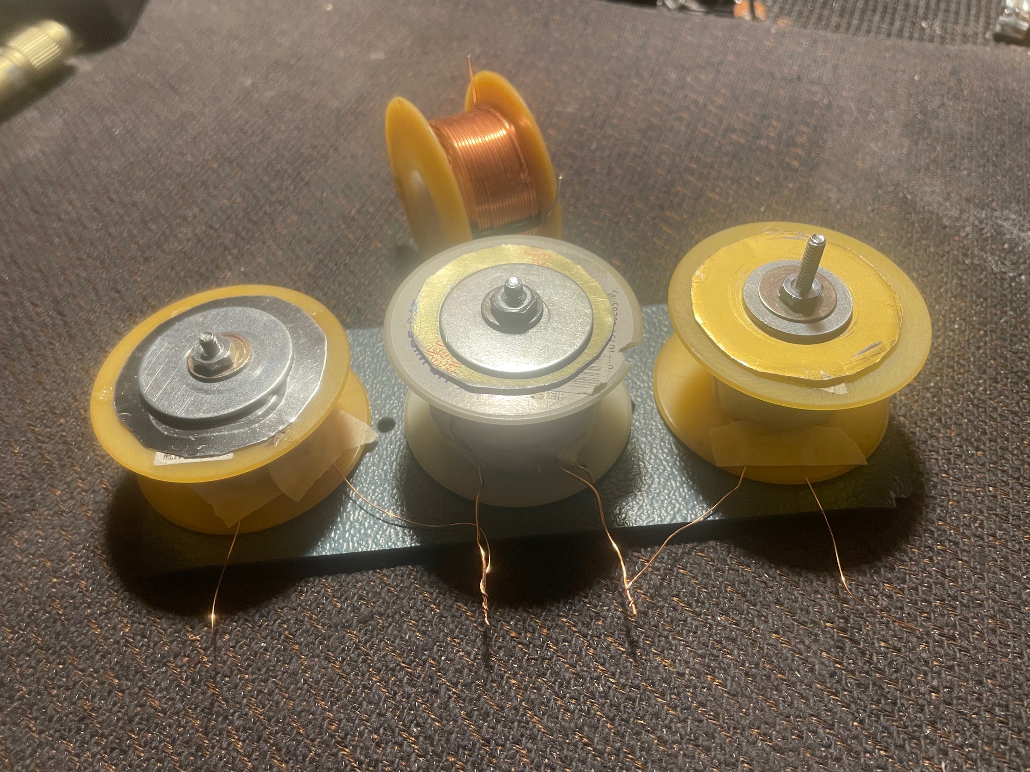
In order to do further testing I had to make a new aluminum baseplate that would hold two to three inductor coils approx. the same distance apart
as in Allan's units. Since the 1mH inductor I ordered was taking a long time to arrive I just hand wound another one with a little smaller gage wire than the first one
I made (approx. 24 AWG). I ended up with exactly 1mH. The DC resistance between the two coils of different gage wire aren't too dissimilar, but both are much
higher than the coil I ordered. The series inductance between the two coils equaled the sum of the two individually. The inductance of the new 1mH coil I made went up
roughly 50% when it was mounted to the baseplate. I will compare that to the one I ordered when it arrives. I am not sure that the results will be that much different
from what I've done here.
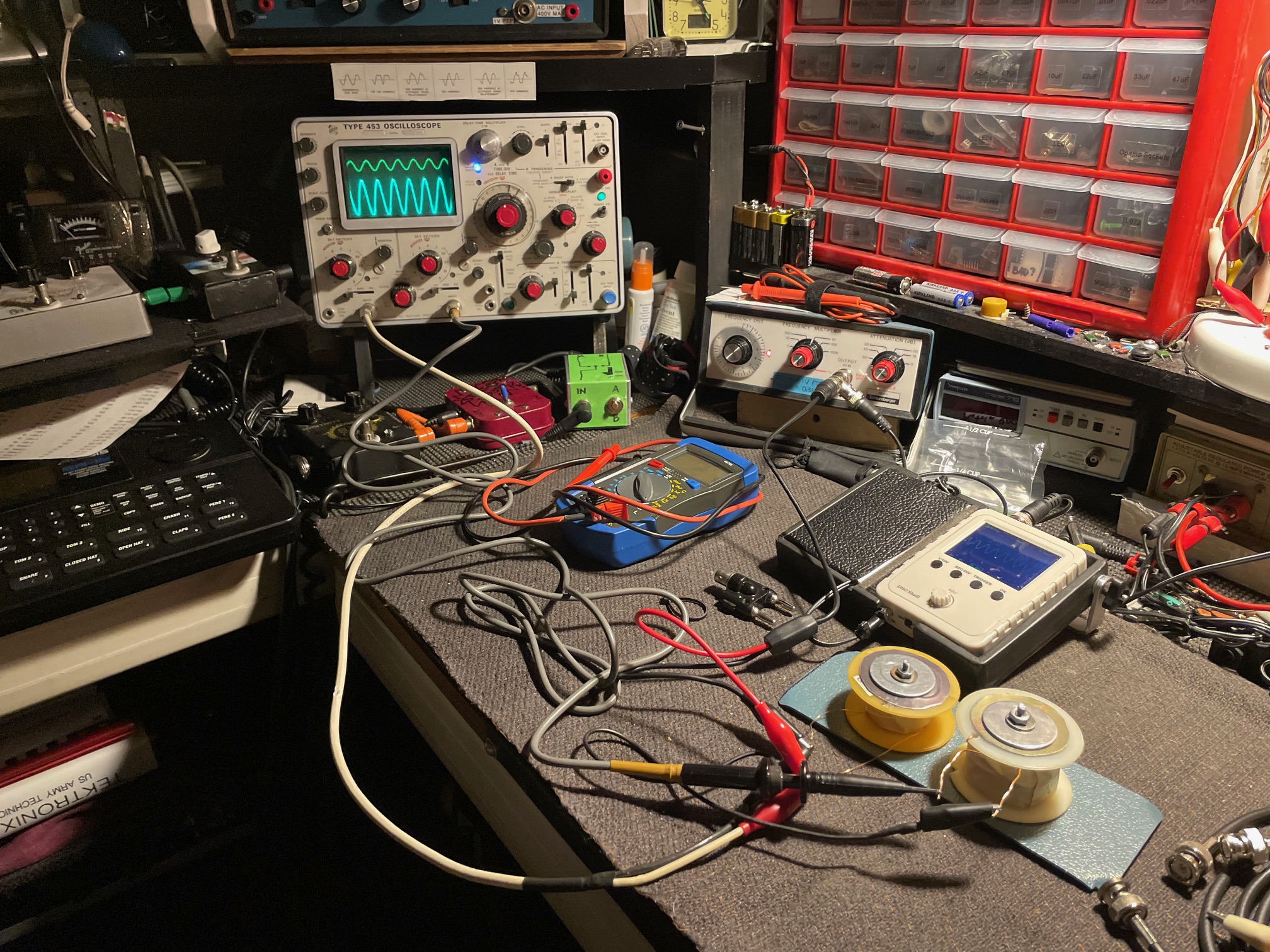
The main thing I wanted to do here is to see if there was any crosstalk (mutual inductance) between the two coils when mounted on an aluminum
baseplate. There is indeed some crosstalk occuring between adjacent coils. The crosstalk occurring on the adjacent coil with no signal going thru it (top of o'scope
screen) is about 25-30% of the amplitude of the coil with the signal from the function generator going thru it (bottom of o'scope screen).
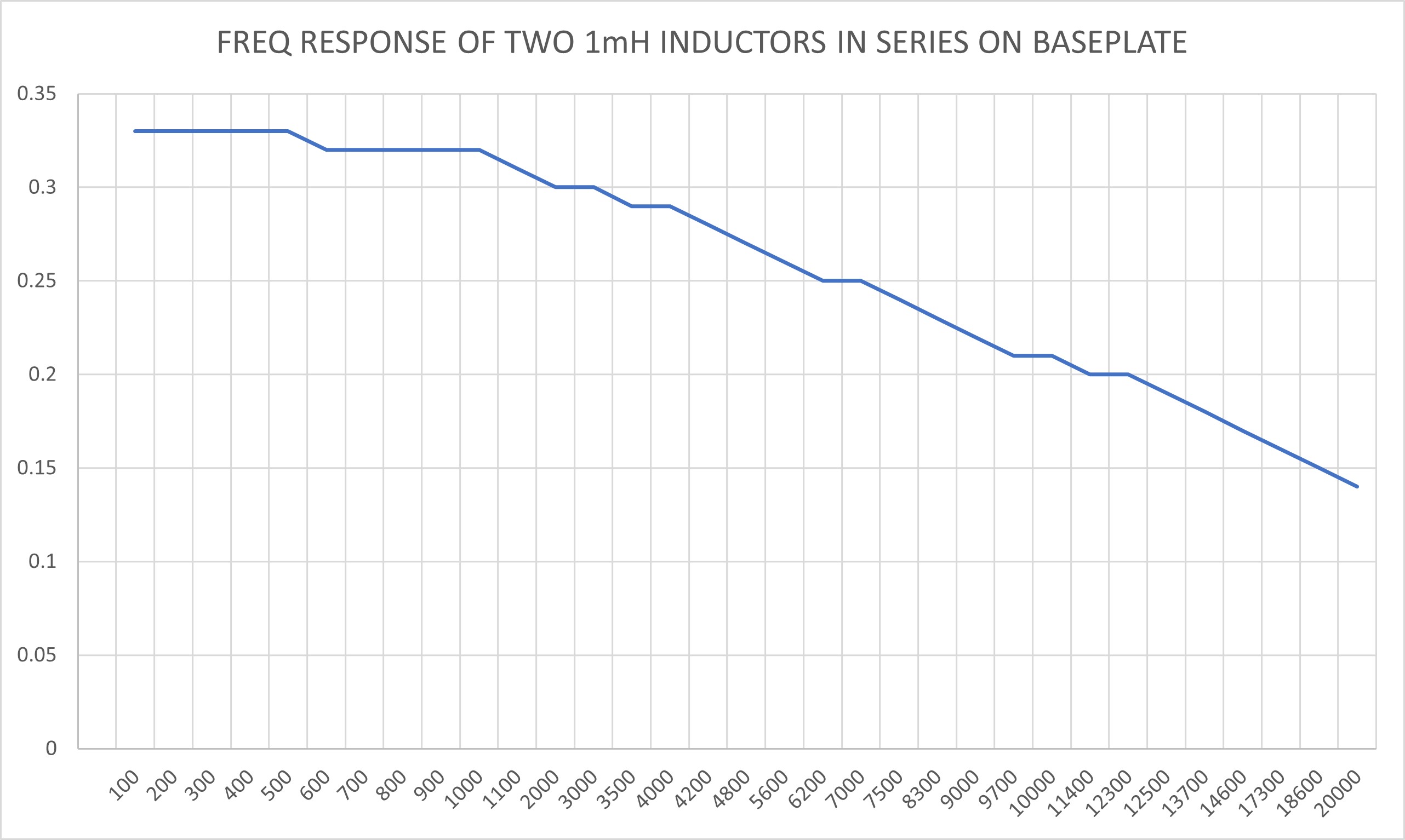
While I was at it I plotted the frequency response. Left side is amplitude of RMS voltage at the output of the two coils and the bottom is the frequencies.
This was done by feeding the coils with a 1V RMS sine wave. It's fairly flat until around 1kHz, after which it steadily declines. I'm not sure how seven of these
affects the overall frequency response, or if it would change the same way with a higher voltage and much more current than what my function generator can supply,
but it does demonstrate the high frequency attentuation effect of the inductors in the circuit. This would filter out a lot of the nasty sounding stuff in the higher
frequencies and make "the tone" sound smoother and perhaps more "mid-heavy".
Update 12/11/23:
My proper air core inductors arrived today and I did some more measurements. Turns out that with these 200 watt 20 AWG 1.0mH inductors with a DC resistance of 0.73 ohms the apparent inductance goes up only about 20%, so I was actually right on target with my initial hunch. Or so I thought. It turns out in my theoretical clone that the apparent inductance actually measured 42% higher - double what I concluded from this simple test.
I investigated what happens when there are three in series. With three coils, the resonant frequency dropped to about 45 Hz. So, after conducting
this series of experiments it turns out that the height of the coil, the wire gage and DC resistance have a significant effect on what happens with the inductance.
Less turns with larger wire equals less losses due to the screws, washers and nuts. It's also likely that my imperfect hand wound coils are very inefficient compared
to the perfectly wound air core inductor beyond.