Allan Holdsworth Harness Circuit Analysis
By Paul Marossy
Created 11/29/23
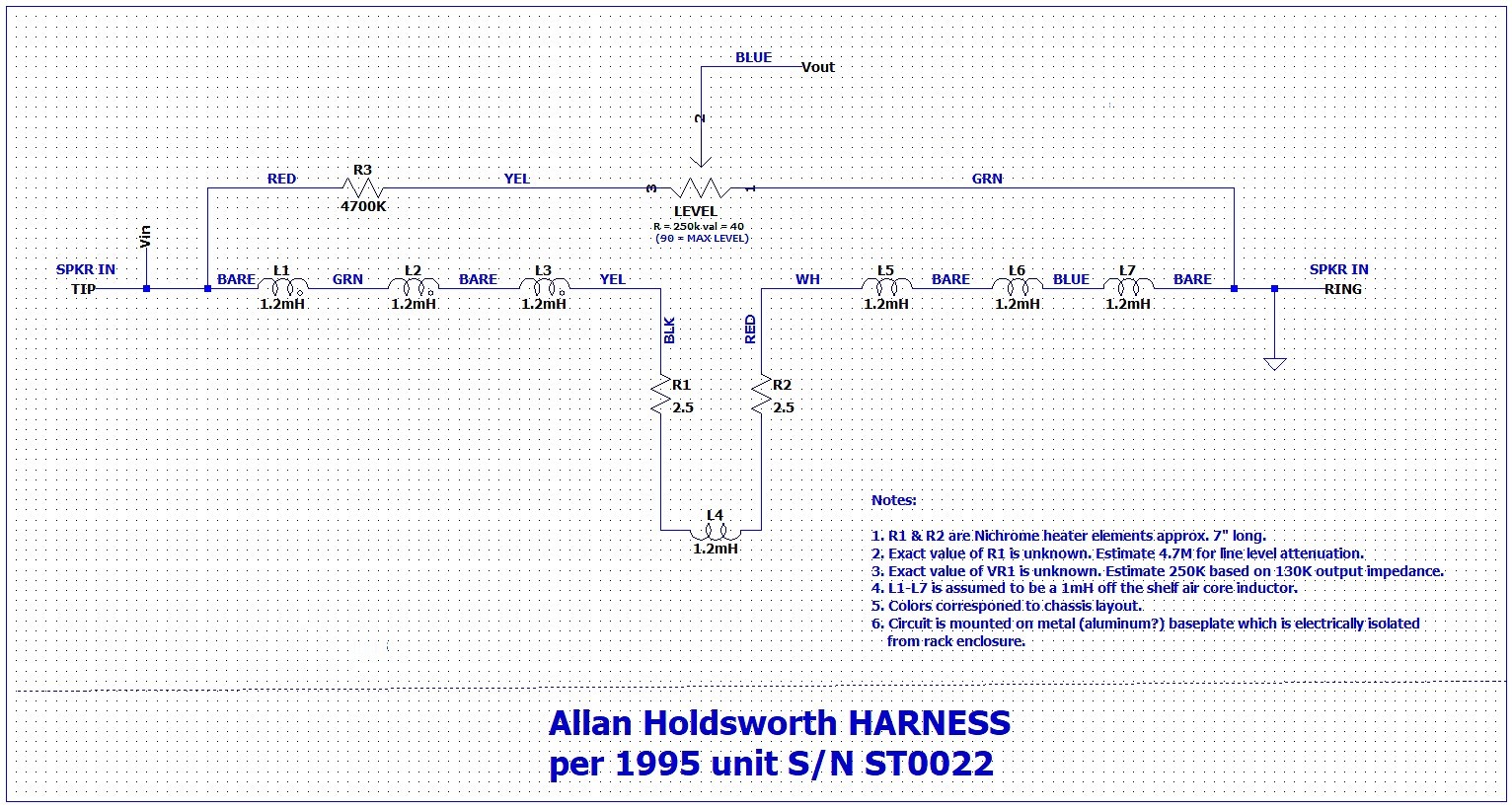
Below is the schematic (you can click on the image to see it larger). This is a passive reactive load for the amplifier. As you can see it's just several of these 1mH inductors in series with the
heating elements in the center of the loop. The signal from the tip of the input jack eventually makes it back to the ring, which completes the circuit. This is
essentially what approximates the guitar amp speaker. The level control is taken straight off the input jack. Note that I gave the inductors a value of 1.2mH, which is what I estimate the 1mH inductors may actually be in reality due to the way they are fastened to the baseplate. It should be noted that my value of 1mH is based on some scribbles Allan made on one of his personal units, but I have also seen one of his units that said it contained seven 1.5mH chokes. For now I am going to stick with 1mH.
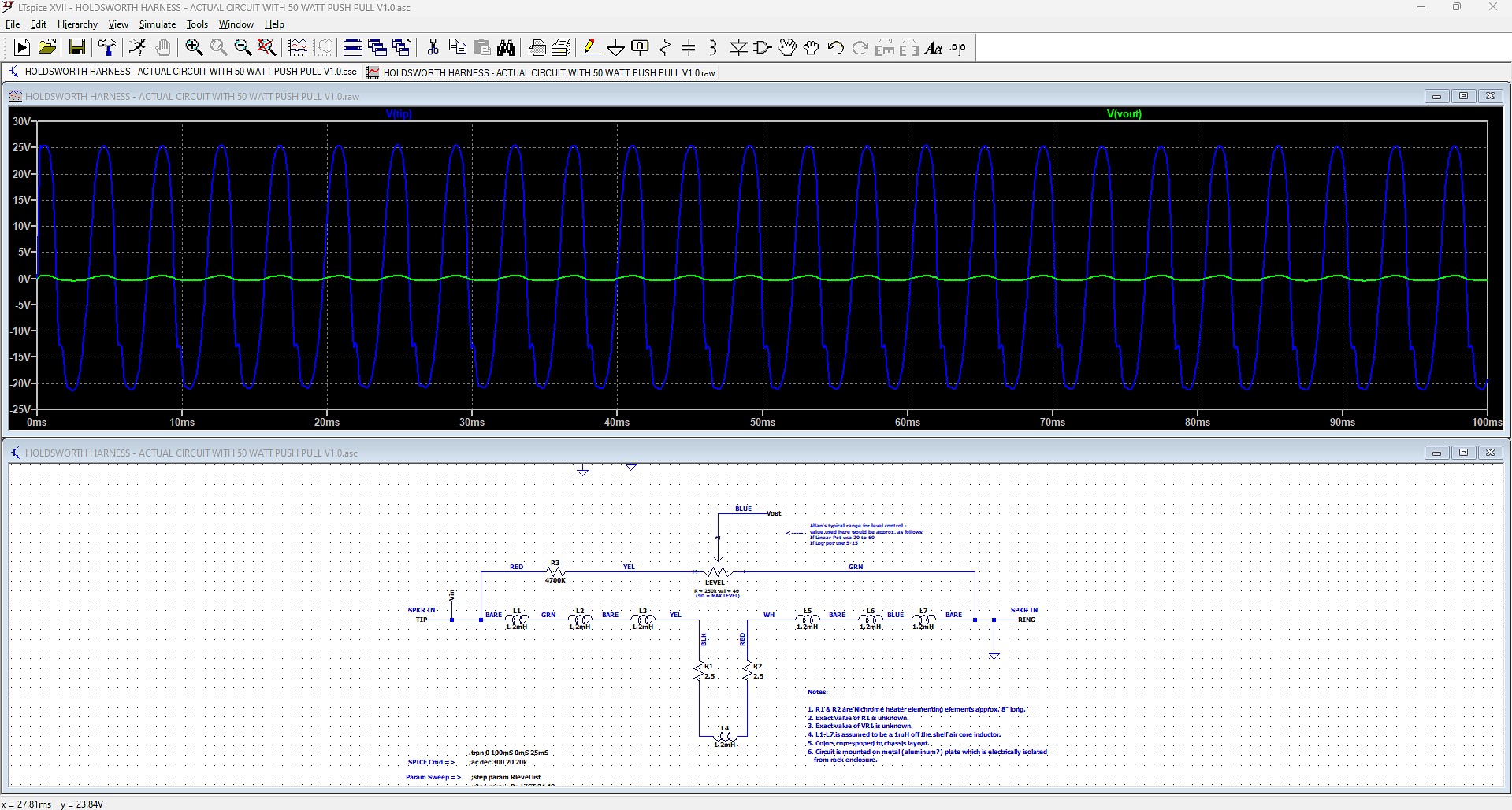
Below we can get an idea of just how much this circuit has to attenuate the signal to get a line level output. The voltage at the input of the circuit is about 46 volts
PTP (18V RMS). With a 4.7M resistor at the input of VR1 we can get a line level signal of up to about 2V PTP. A lower value could be enough to present a massive input to whatever is connected to the
output jack. This is likely one reason why in the owner's manual Allan really emphasized starting out with the level control very low and slowly turning it up to get the desired outcome. The other danger with this device is that you have to be careful to not fry your output transformer. This circuit was initially designed so that you could turn up a Mesa Boogie to six and get transformer saturation, "sag" and power tube distortion, silently. Obviously it works with other amps too, but each amp has to be treated on a case by case basis.
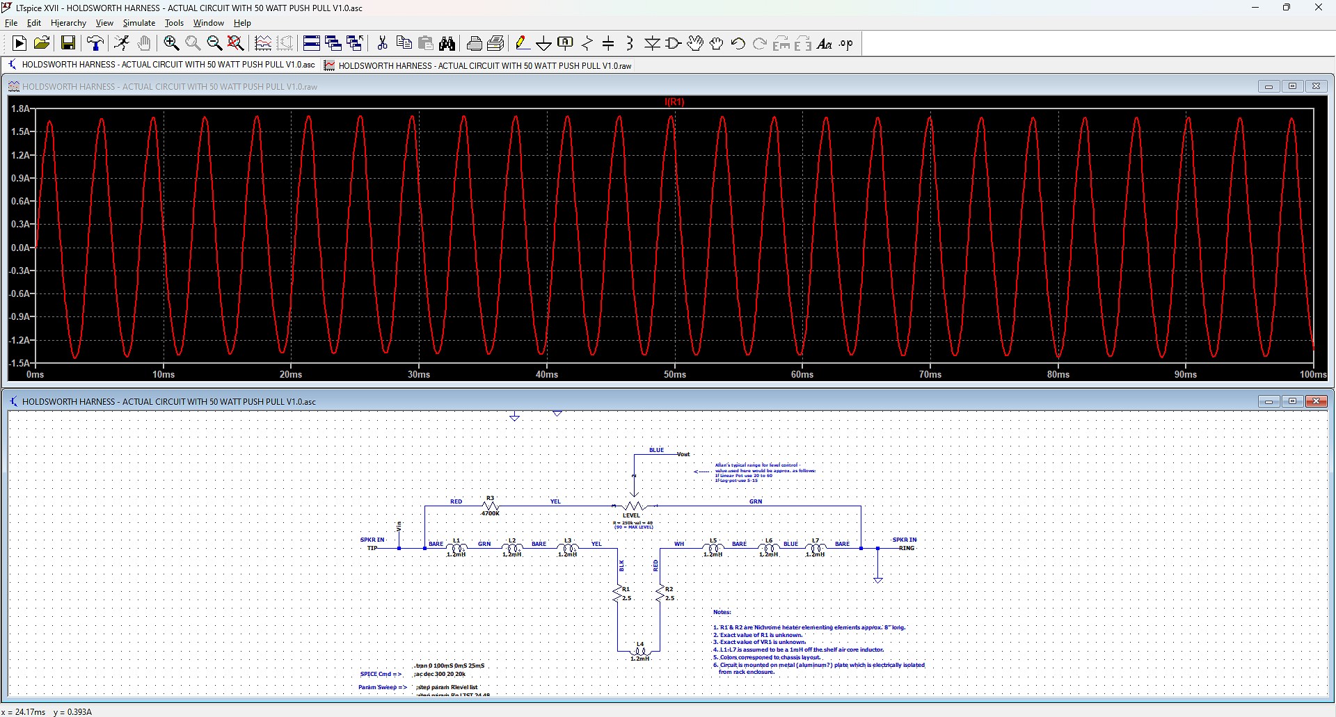
Below we can get an idea of how much current those heating elements might see in ordinary use. Here we can see PTP current is approx. 3.3 amps (1.08A RMS). This equates to about 50 watts. A 100 watt amp would double these numbers. This aspect of the circuit is difficult to
simulate without knowing the actual specs of the heating elements, and it could vary quite a lot with gage of the Nichrome wire, length, etc. But at least we can get an idea of
the job that it needs to do.
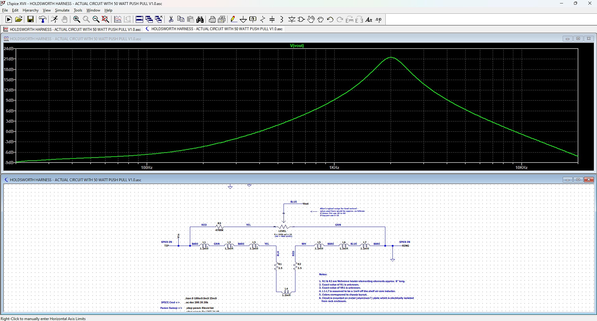
Finally, we can see the frequency curve. Here also some guesses had to be made. One big unknown is what effect the metal bits around the air core inductors has on the actual inductance
value. The presence of the large self-locking washer, long bolt and being mounted on a metal baseplate certainly will have some effect on the frequency response. The inductors will likely be somewhat "lossy". This would tend to increase the inductance, which will
attenuate more of the high frequencies. I took a guess on how much affect that may have. My current working theory is that it increases the inductance by about 20%. In the plot below, we can see that the low frequency response isn't great, and there is a peak at about 2kHz after which the high frequencies are steadily attenuated.
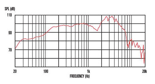
Compare that with the frequency response of one of Allan's favorite speakers, the Celestion G12-65s in a Marshall 4x12 speaker cab. There are two peaks at about 2.5kHz & 3.5kHz but all of the frequencies between 20Hz and 2.5kHz of the G12-65 are quite different. This would have worked in Allan's favor because he used to like running something like a Mesa Boogie head into The Harness, and then putting the output of The Harness into a preamp with parametric EQ where he could dial in exactly the type of frequency response he wanted before sending the output of that to the various signal processors he employed, and then finally into another guitar amp with an actual speaker. I don't know what he did in later years but this
elaborate arrangement that he used in the 90s is probably one reason why it's difficult to convincingly replicate his sound. He went to extraordinary lengths to shape the "tone" into something that didn't sound so much like a guitar.
Hopefully this gives you a basic understanding of what The Harness does. It would be most interesting to see how close I came with these estimations. If you have a Harness and want to
"contribute to science", please get in touch with me! I still need a bit more info on a few items to really nail this down. The three items I need to verify is the value of R1, the value/taper of VR1 and especially the Nichrome wire gage/diameter.
It took quite a lot of time, educated guess work and consultation with some people that are far more knowledgeable than myself to come up
with a basic circuit analysis. While the circuit is simple there is a fairly complex set of interactions going on. It's especially difficult to do a circuit analysis when you don't possess the device you are analyzing, but I have reverse
engineered a few things in the past with only some pictures. The estimates made seem reasonable but there are still a lot of unanswered questions.
Hopefully someday in the future someone that owns one will be willing to fill in the blanks but for now I think we have a reasonable approximation of what
The Harness does. Keep in mind that I only created these webpages in a quest to satisfy my own curiosity, to share what I have discovered with the curious, and to
shed some light on Allan's interesting creation. If you decide to try to DIY this relatively simple device, you do so at your own risk. You could end up with an amp
that has a smoked output transformer.
To do the circuit analysis, I used LTSpice. In this simulation I used a 50 watt Marshall-esque EL-34 push pull circuit to simulate an amplifier output section
connected to The Harness. Since I don't know the values of R1, VR1 or anything about the heating elements I had to make some educated guesses. It seems that
a 4.7M resistor at the input of the level control (VR1) is needed to get a line level attenuation. For the level control, it appears that a 250K pot would have
been used. This is based on the stated 130K output impedance. This would conincide with the output impedance with a linear level control at 50%. I don't know the
taper of the pot used but I would assume that it's a log taper since it's basically a volume control, but maybe not.
The $64,000 question is those Nichrome heating elements. I have no idea
what gage the wire is, what the resistance per foot is, etc. but the actual value of them is probably somewhere between 1.5 to 4 ohms each. According to Allan
those are "what takes the load", but in reality the 1mH air core inductors are also taking some of that load. Those inductors are likely off the shelf speaker crossover
inductors that are rated for 200-300 watts. What makes these heating elements an interesting facet of the design is that their resistance and current handling capacity will change somewhat with
temperature. By how much? It's not really possible to definitively answer that question without knowing the specifications of this nichrome wire.
Special thanks has to go to Rob S. at the DIYstompboxes forum for his expertise in all of this.