|
This is a module that combines tube and solid state components to
acheive a module with more crunch and sizzle, with an emphasis on
odd order harmonics. This is supposed to sound like a modified
Marshall. This module is basically the same as the High Gain module
except that in place of the 1K resistor that would normally
be on Pin 8 (cathode of second triode) there are some current
limiting diodes. The ones Seymour Duncan used are marked " CIL 1301". (Thanks to Stefan Schroder in Germany for
the verification of the markings on those diodes!)
I have recently received new information from Kevin Beller (chief engineer,
Seymour Duncan) that these diodes were made by Teledyne and are in fact
1mA current limiting diodes. This confirms what I have been told by other
sources about what these diodes probably were. You could easily mod an existing
Hi Gain module into a Hi Gain Hybrid by removing the cathode resistors and
replacing them with some CCL1000 current limiting diodes made by Central
Semiconductor. Here is a data sheet on that diode. I have also been informed that Vishay Siliconix J505 current regulator diodes will also work for this module.
Shown below is a picture of the various components.
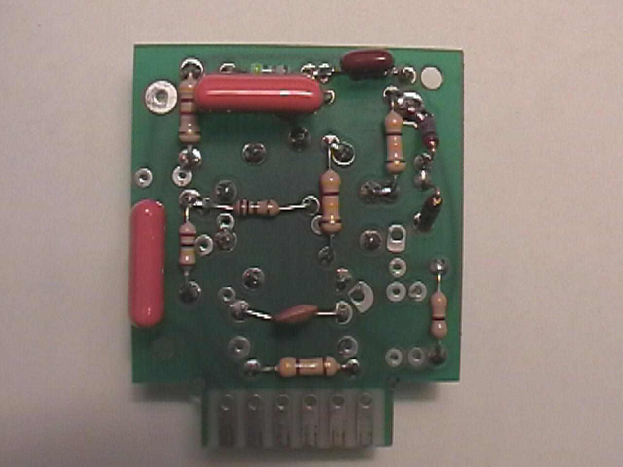
Photos contributed by Tim Pruitt
I have learned a couple of new facts about this module thanks to
Larry Monroe in Blountsville, Alabama. (Larry actually mailed me
a module for me to look at and send back for verification of the
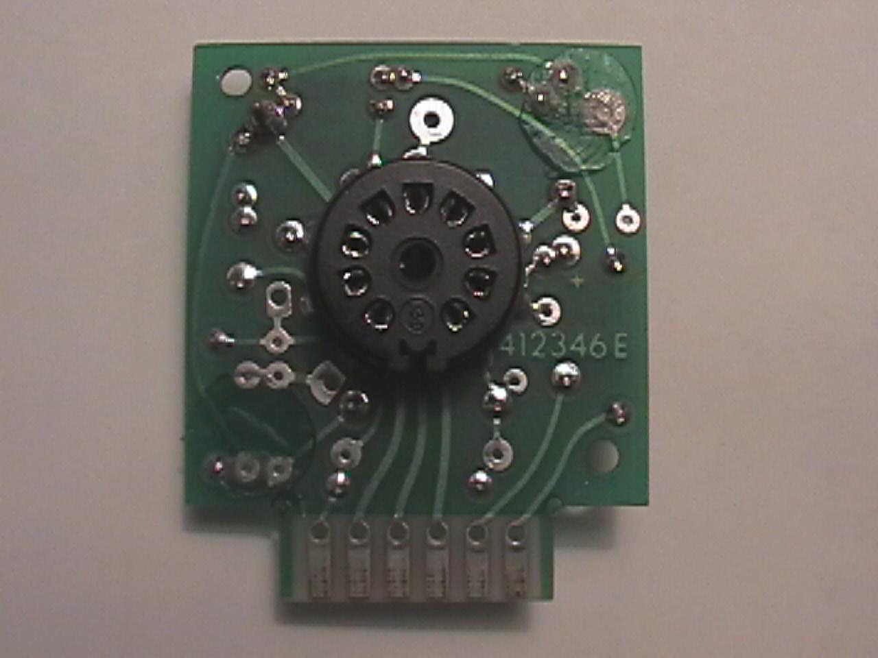
circuitry!) There apparently was two production runs, as the two
PCB's I have seen for this module are different from eachother.
They have slightly different PCB layouts and the traces have been
redesigned a little bit, but the circuits are still exactly the
same functionally. You can tell them apart easily, as one version
has a green coating on it with very shiny traces, and the other
version of it has a cream colored PCB which doesn't possess the
same high quality as the green version. In fact, it appears to be
the exact same PCB as the normal Hi-Gain module. I suspect the
green version is a later production run.
Below is a link to a verified schematic and component layout.
Many thanks to Rick Erickson for the schematic!
Component Layout/Schematic
PCB Layout
Back To Previous Page
| 