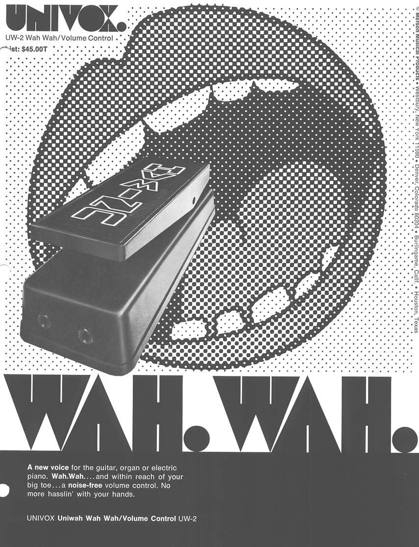
The Univox Uniwah UW-2 Wah Pedal
Last updated 02/23/24
By Paul Marossy
This wah pedal made by Univox sometime in the very late 60s/early 70s isn't on most guitarist's radar, and for those who know about it, it's not considered to
be anything special or to sound great. When they work, they sound pretty good. When they're not working as intended, or parts are out of spec due to age, it doesn't
sound good. Some websites claim that this is just another Crybaby copy. Nothing could be farther than the truth!
What is very interesting about this wah pedal is the circuit that it uses. It is one of only two wah pedals I am aware of that use a
variable inductor (the
Kay "wah wah"
is another example). It is not just another conventional inductor based circuit, such as the aforementioned Crybaby. It also utilizes a light bulb/LDR combo
like its more famous relative, the Univibe, but only for the volume pedal function. Also interesting are the mechanical aspects of the enclosure and how the thing works in general. You can see the factory
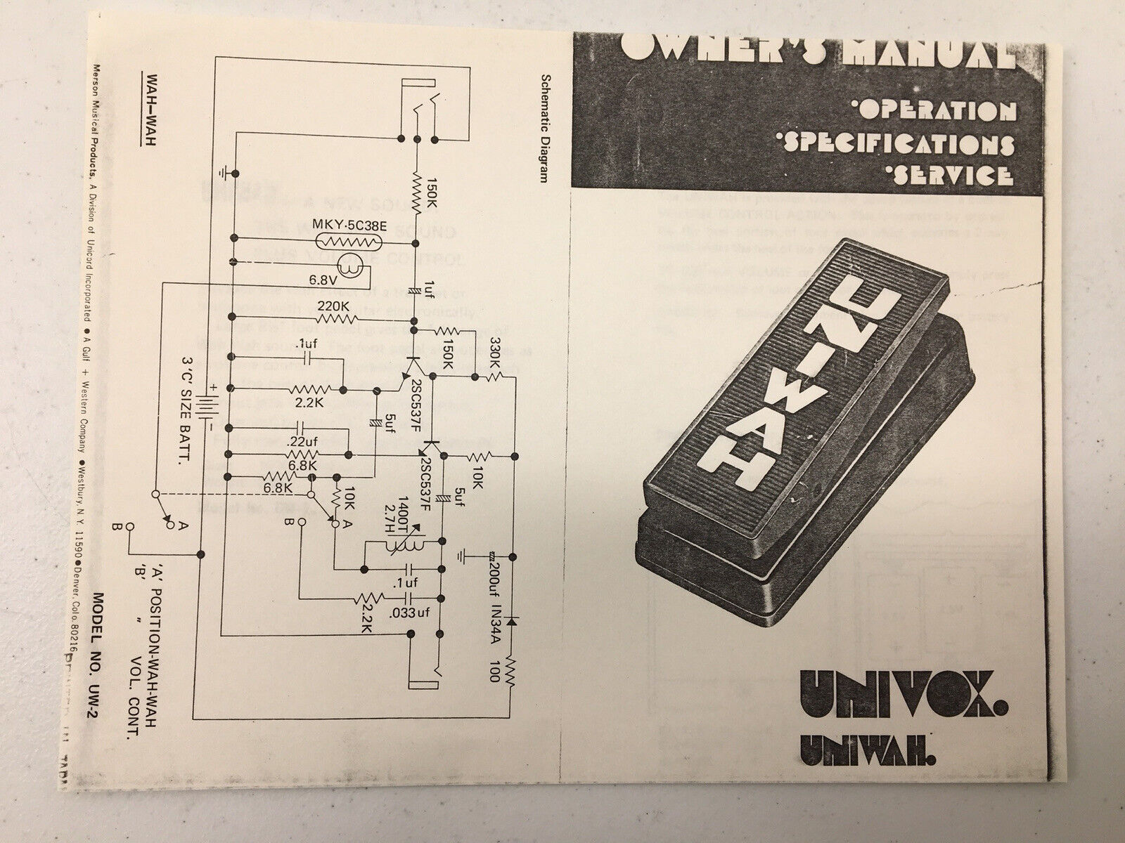
schematic at the bottom of this page if you want to learn more about it. One thing I like about it is that there is no potentiometer to wear out or go scratchy.
Below is some detailed information on this unique beast:
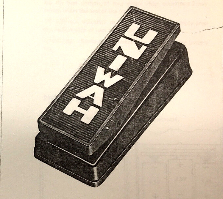 |
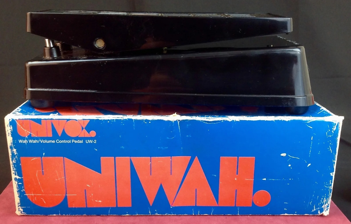
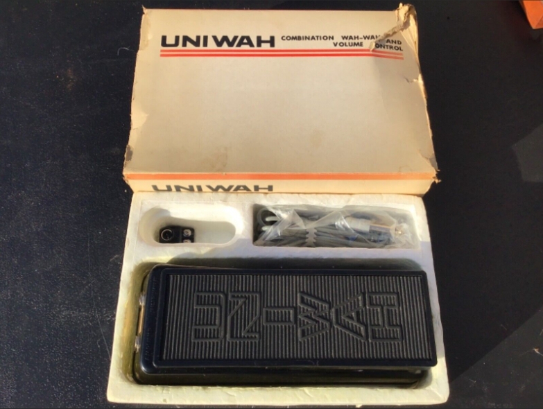
Here is the Uniwah as presented on one of the versions of the owner's manual. I think they're kinda cool. The shell is made of a thick and pretty tough "impact proof" plastic. These were made in Japan for Merson Musical Products, the parent company of Univox. It is about the same physcial size as a Crybaby, but the heel end of the treadle is taller (around 1/2" or so). |
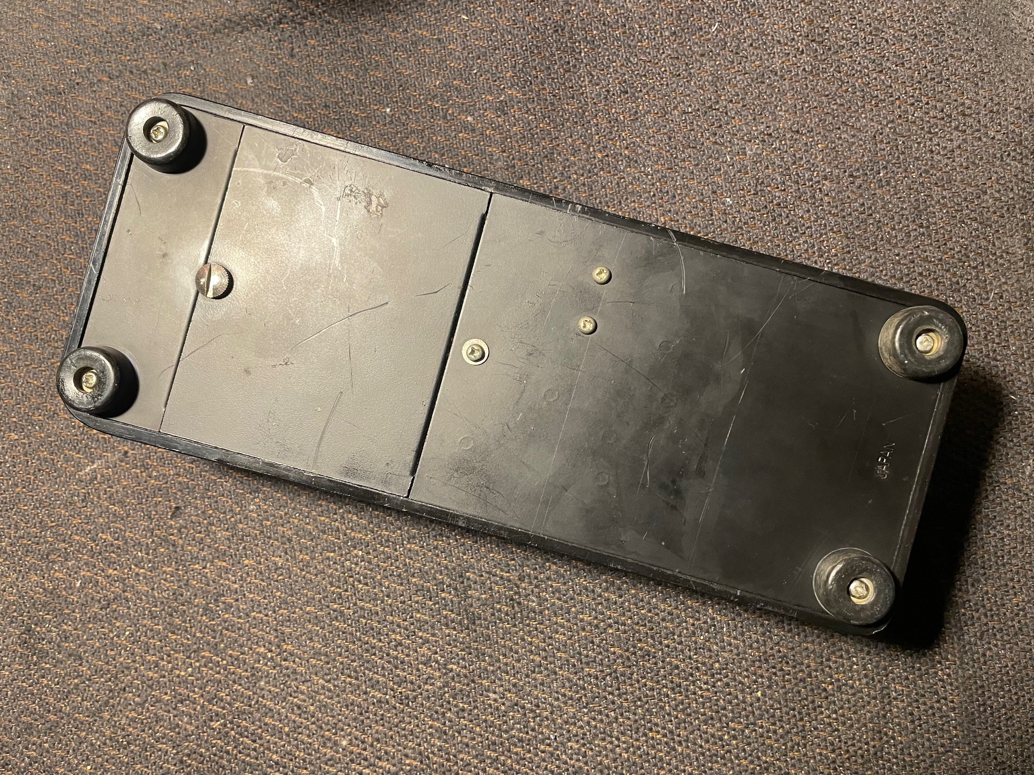 |
Here is a view of the bottom. The battery door is on the left side and the screw has knurled edges, so it's easy to unscrew it with your fingers. |
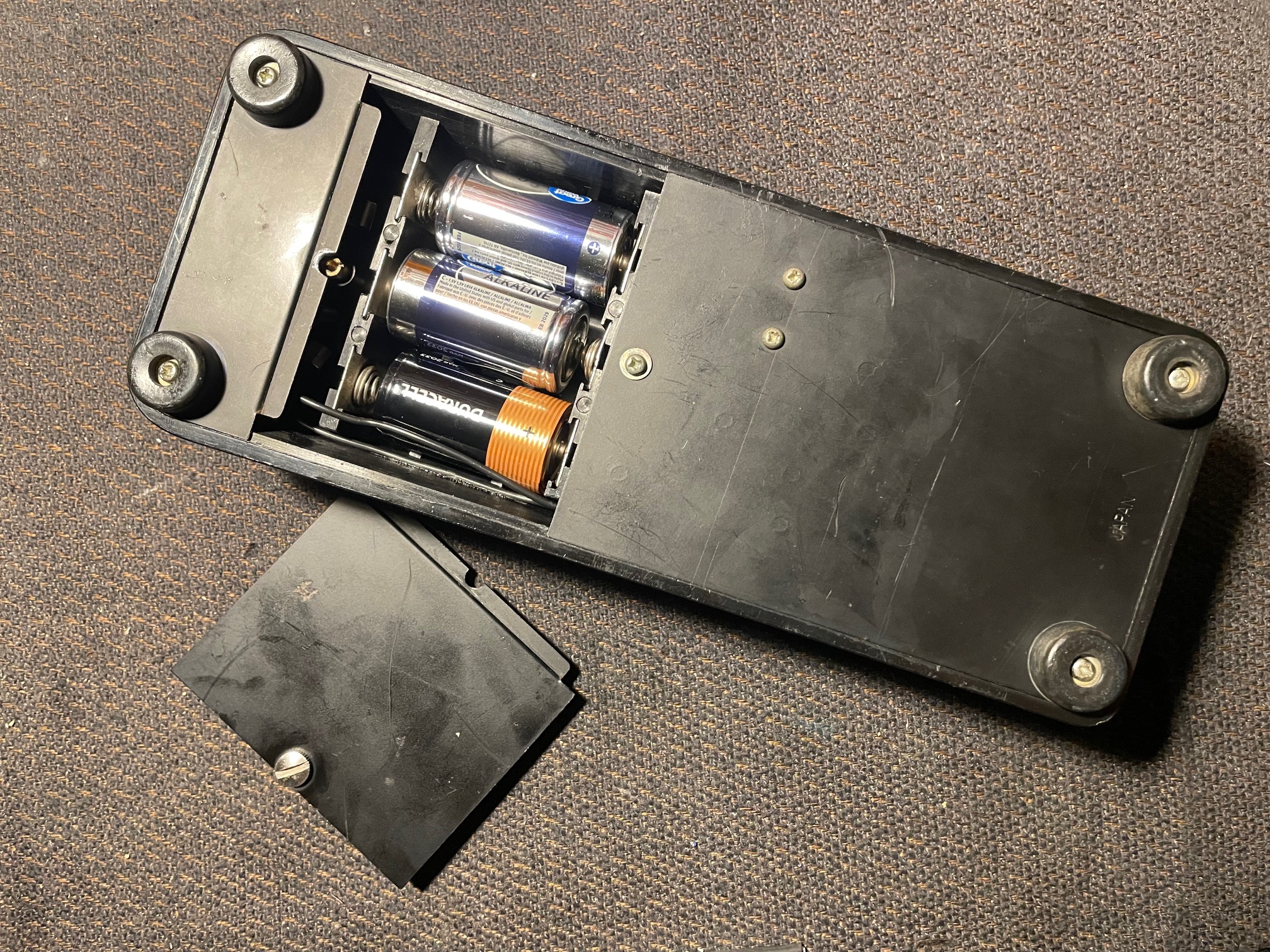 |
Here is the battery door removed, which reveals another quirk of this unique wah pedal - it operates on three C batteries. The working voltage of this circuit is 4.5 volts. |
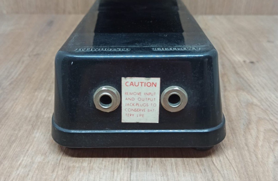 |
When these units were new, they had this label at the 1/4" jacks. A few examples still have this sticker on them. |
 |
The treadle is held onto the shell by this shaft which is secured by a pair C-clips. I removed these so I could take off the treadle to adress something a previous owner did and to give it a thorough cleaning. |
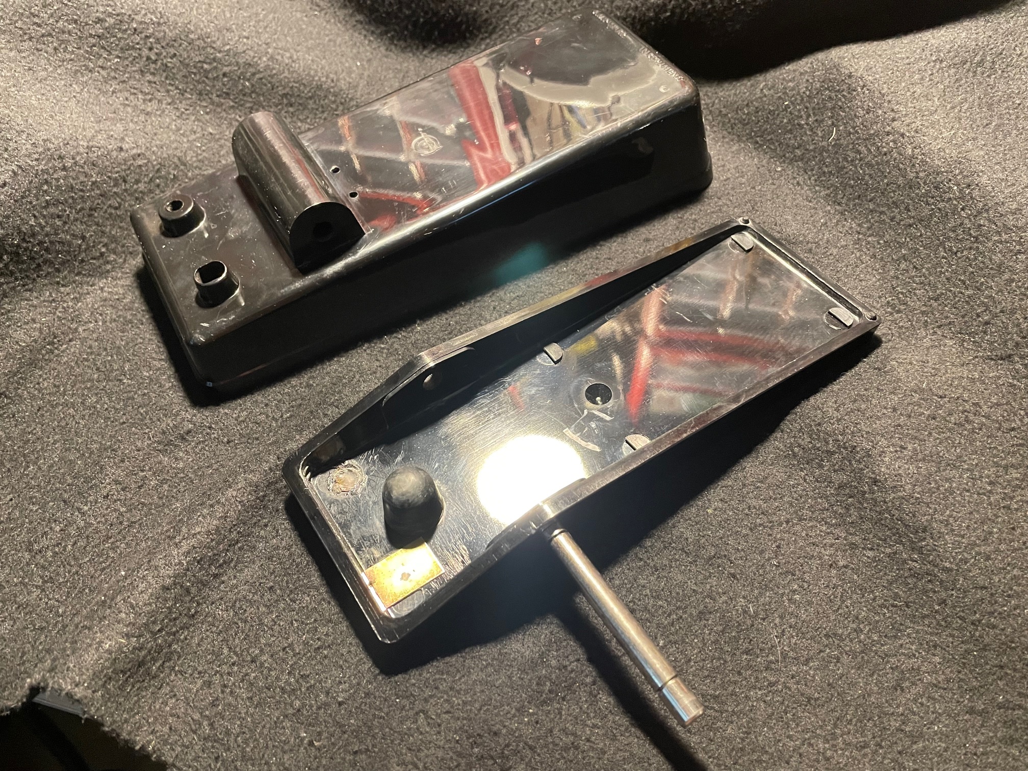 |
The shaft is similar to what is used on the Crybaby - one end is smooth and the other end is knurled. To remove it, it needs to be driven out in the direction shown in this picture. Was suprisingly difficult to get out, but with the help of a little bit of lubrication it finally came out. |
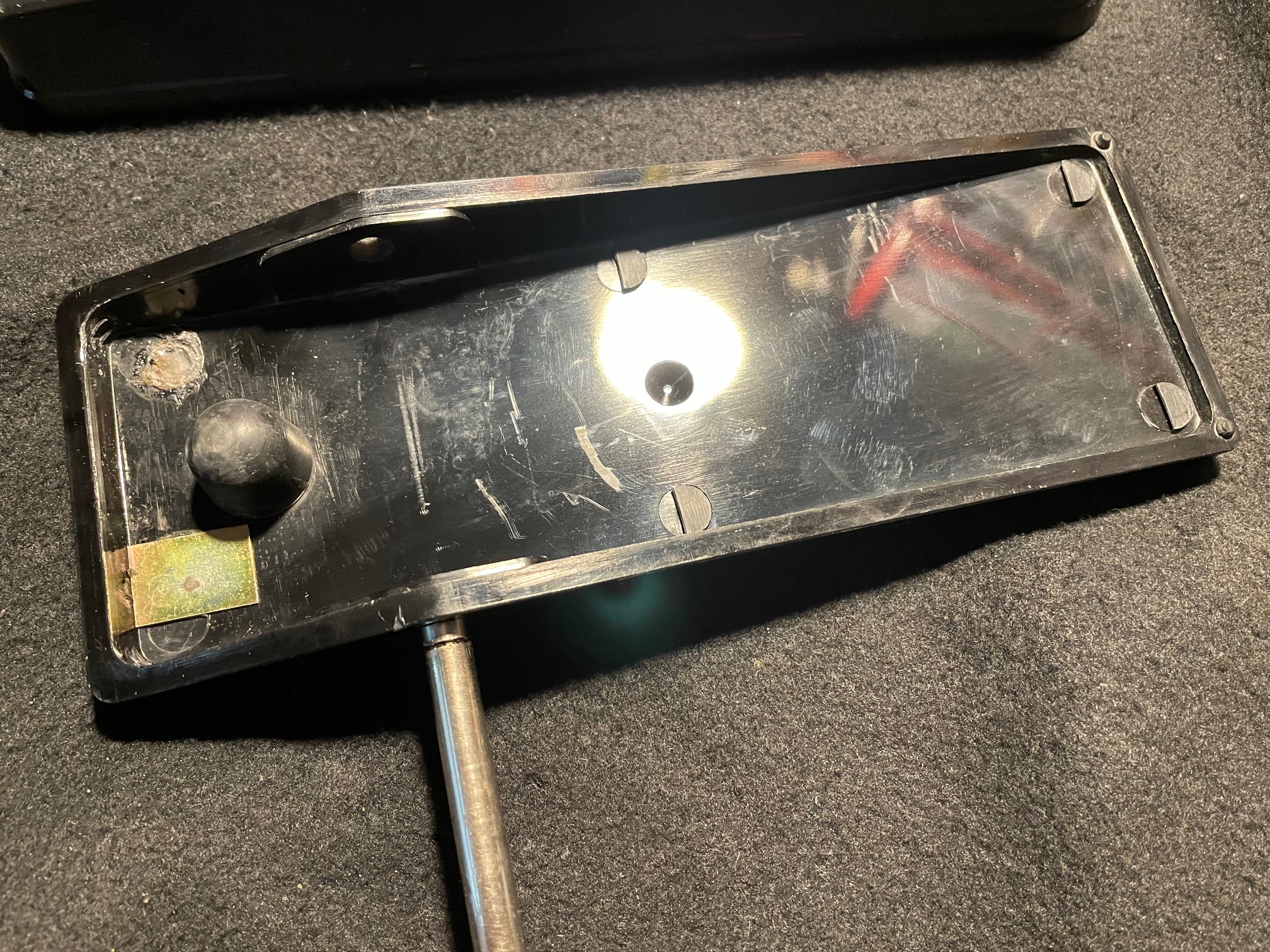 |
The little piece of what I think is brass is for the push-rod actuator, which actuates the flat spring inside. More on that further down the page. |
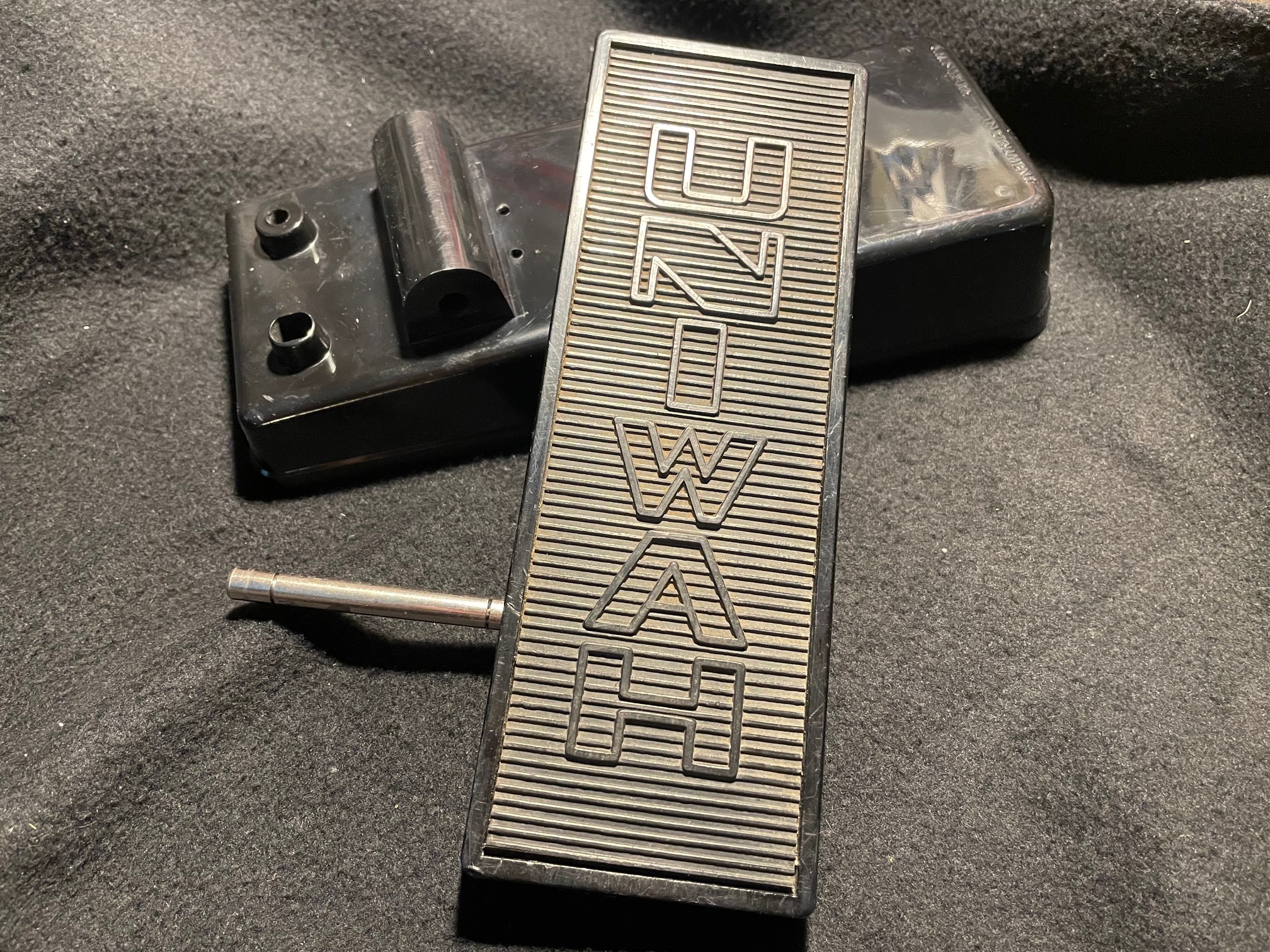 |
Here is the treadle as it would normally been seen. I like how the logo is molded into the rubber foot pad thingie. |
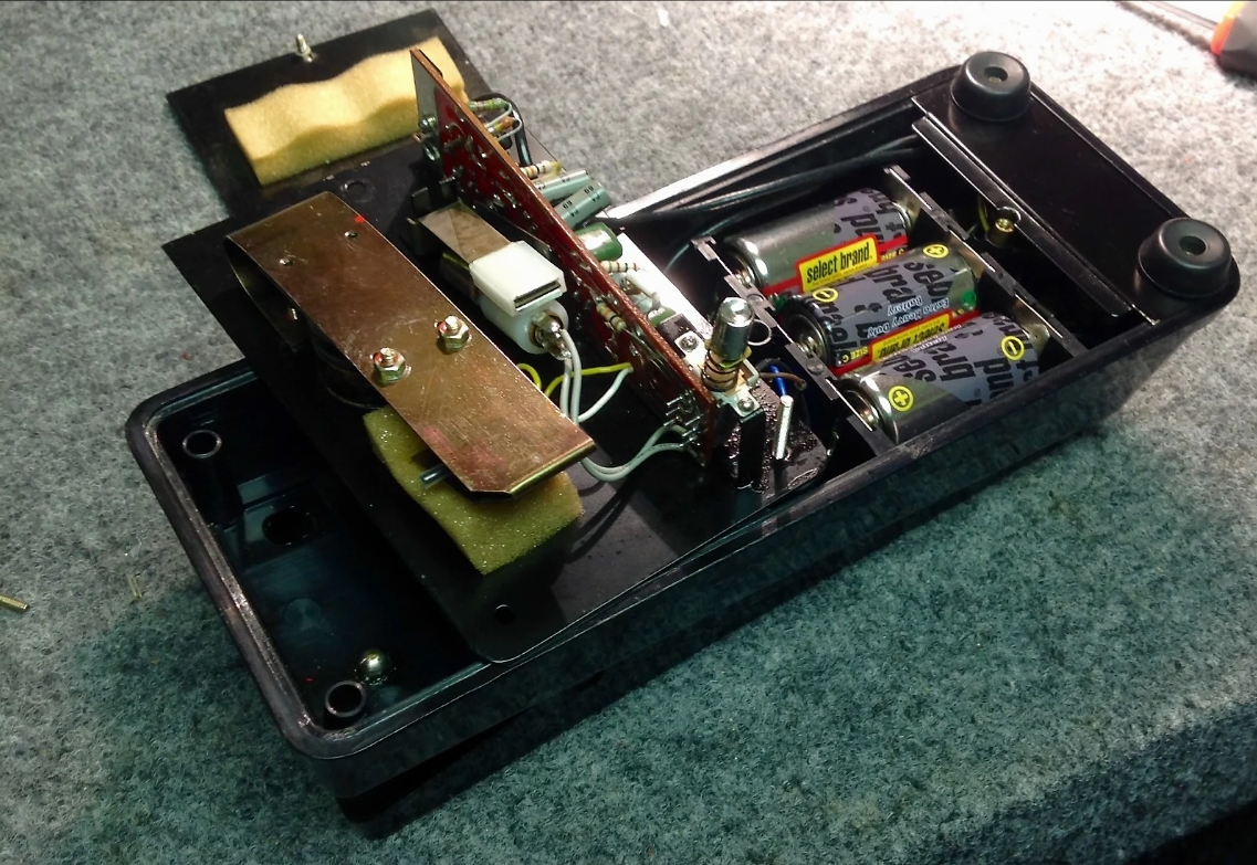 |
By removing three screws, the circuit block is revealed. My unit had a few issues to address, which I will comment on as we go along. |
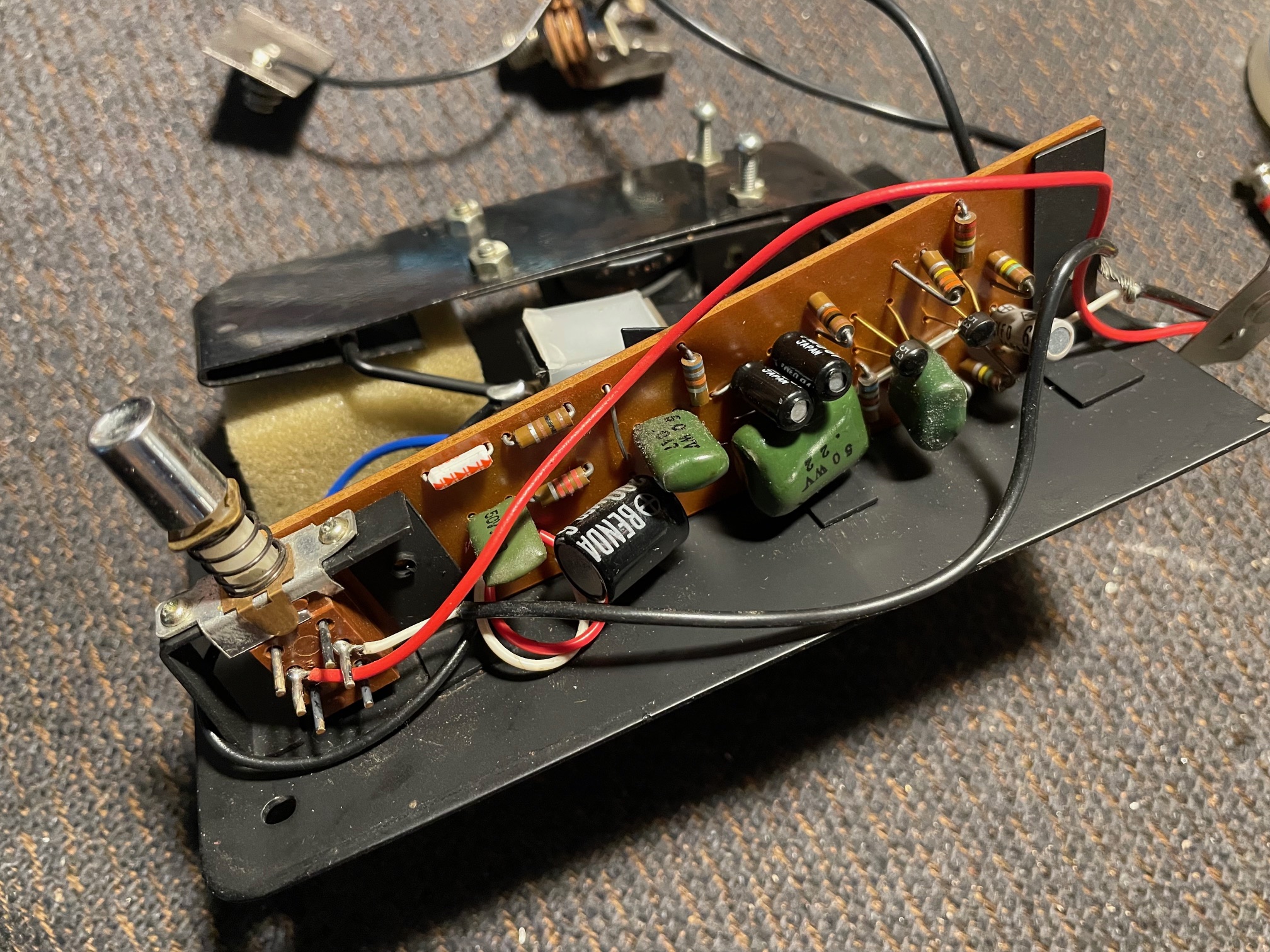 |
Here is the component side of the PCB. Notice that it has slanted edge at the top. The footswitch is very unusual. It's a PCB mounted two-sided DPDT switch. Never seen anything like it. Even though there are 12 pins in reality it's just like a regular DPDT switch but with the ability to have double the number of connections. One side of it is used to switch off the light bulb when the pedal is in "wah wah" mode and the other side does the signal routing. |
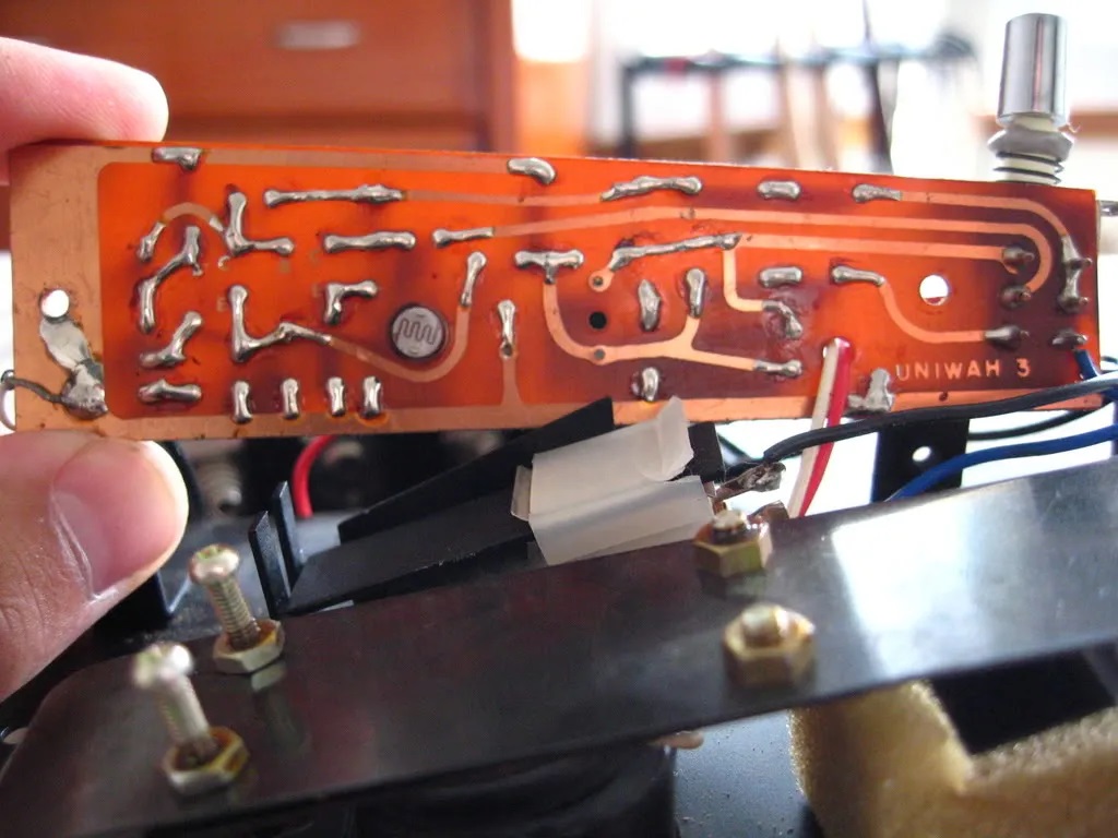 |
This is the copper side of the PCB. There does not appear to be any kind of conformal coating on it. |
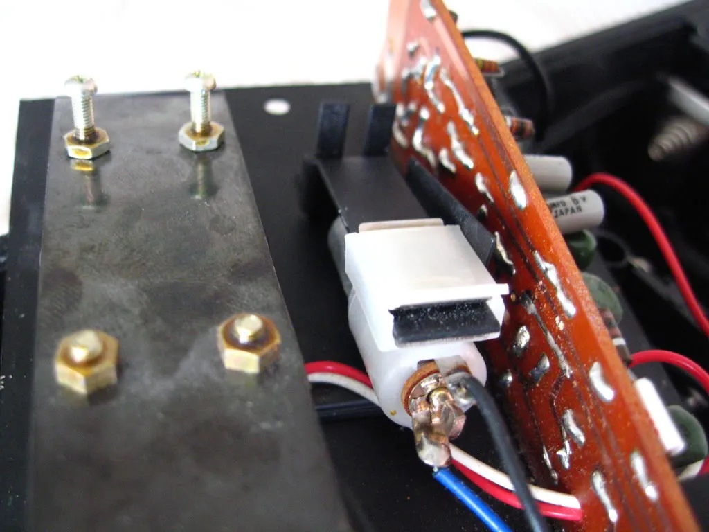 |
This is the arrangement used to secure the 6.8V light bulb. It's a holder that slides on/off a metal tab. It's very easy to remove and change the light bulb. Just be careful to not break the wires where they are soldered on. |
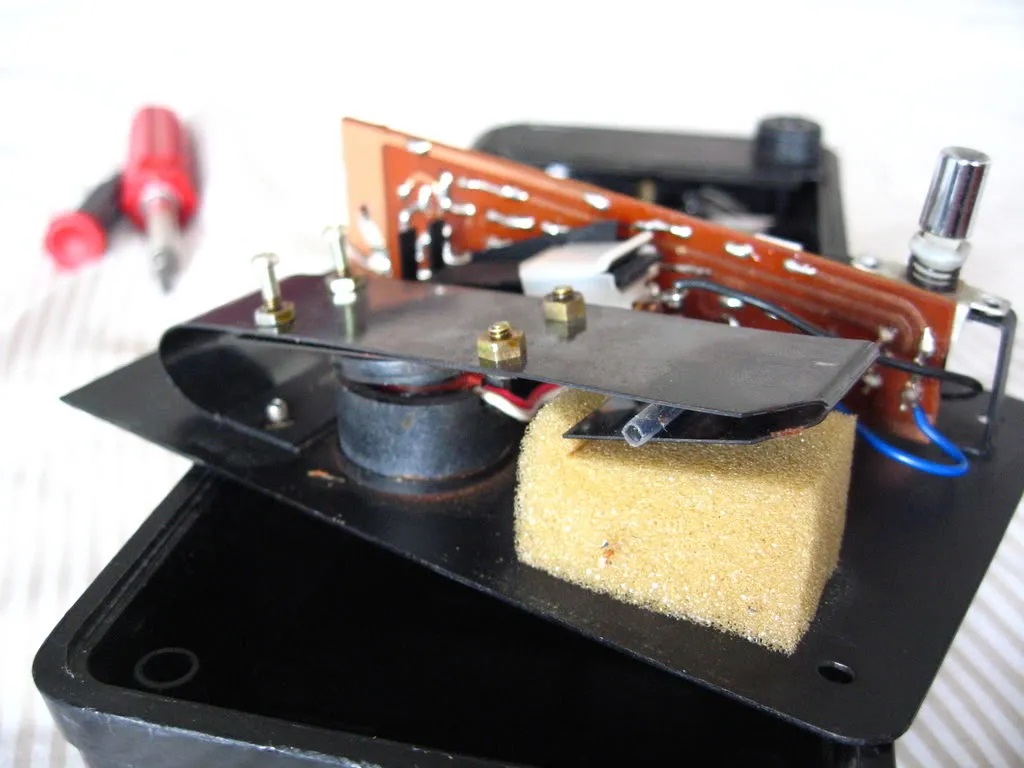 |
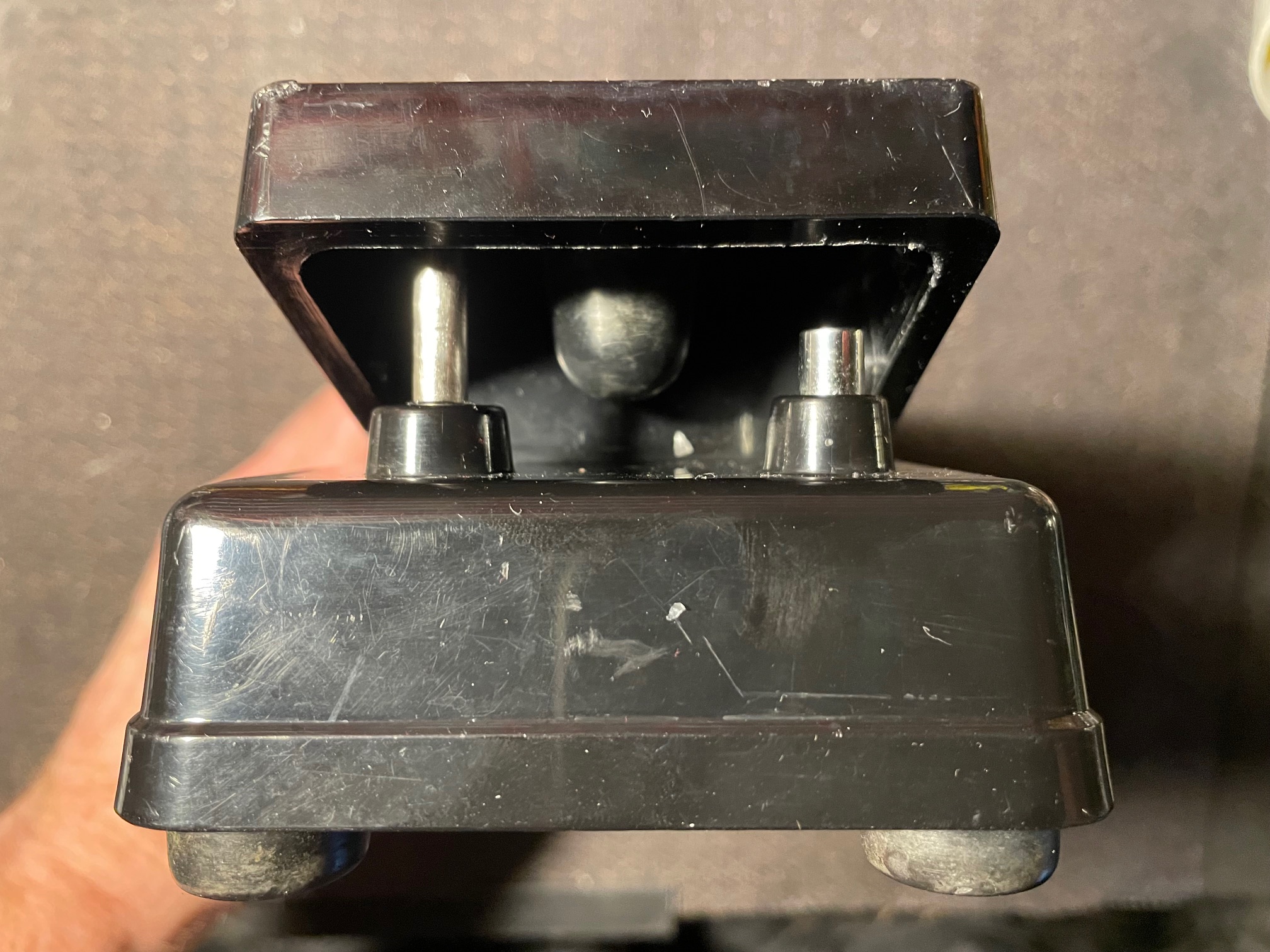
Here is a side view of the flat spring assembly. It's kind of difficult to see but there is a piece of thick bent wire (approx. 3mm dia.) which limits the upward travel. At the other end of this wire is a shutter plate with a triangular cutout which controls how much light the LDR recieves from the bulb and also limits travel in the other direction. |
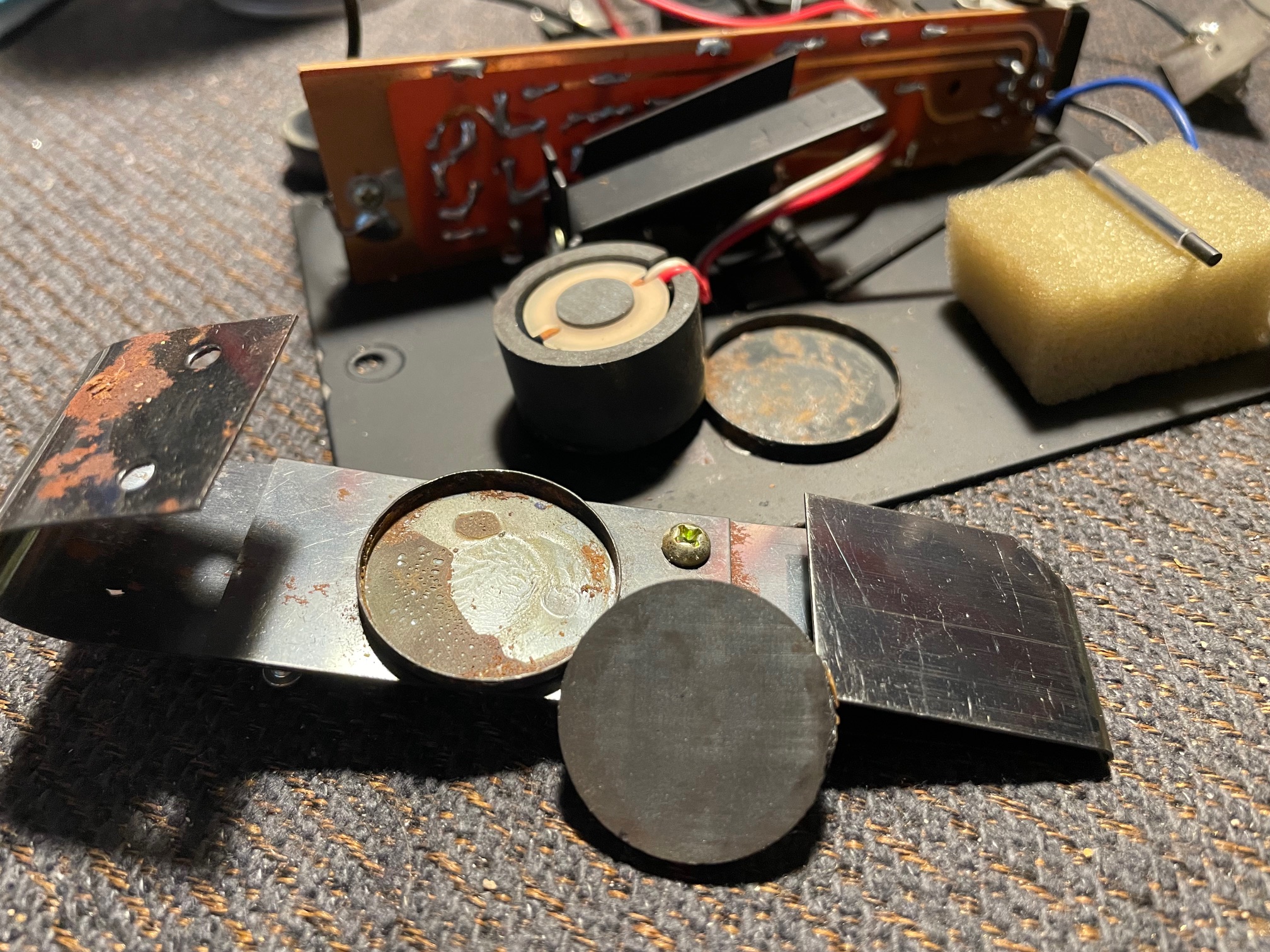 |
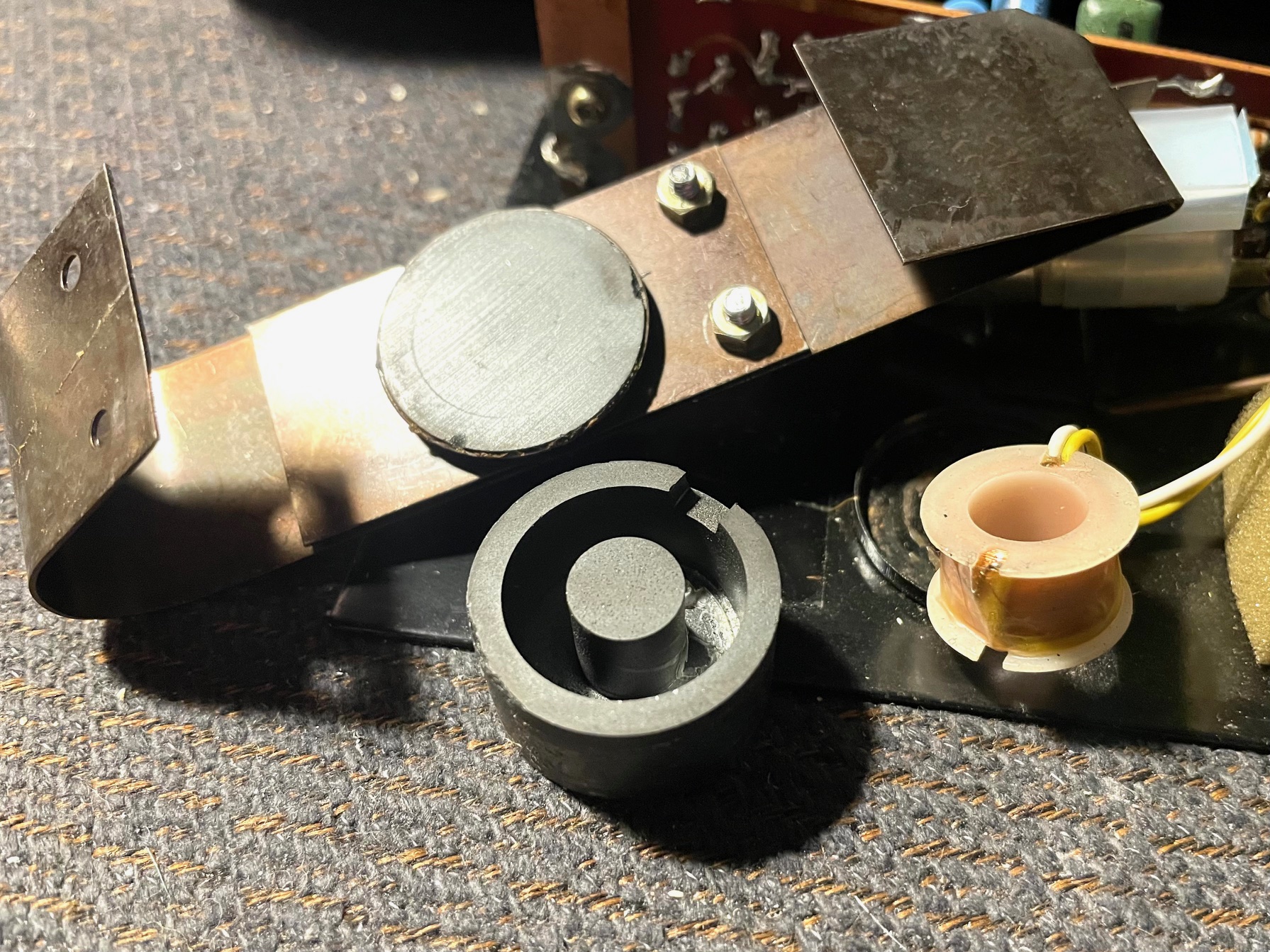
Here is a common problem that these Uniwahs have - the inductor parts coming loose from the housing. When these become unattached it starts to sound weak/bad. To fix mine I used a healthy amount of superglue to affix it to the bottom plate. The round ferrite disc that is attached to the flat spring also commonly comes loose. The remedy was the same, superglue. |
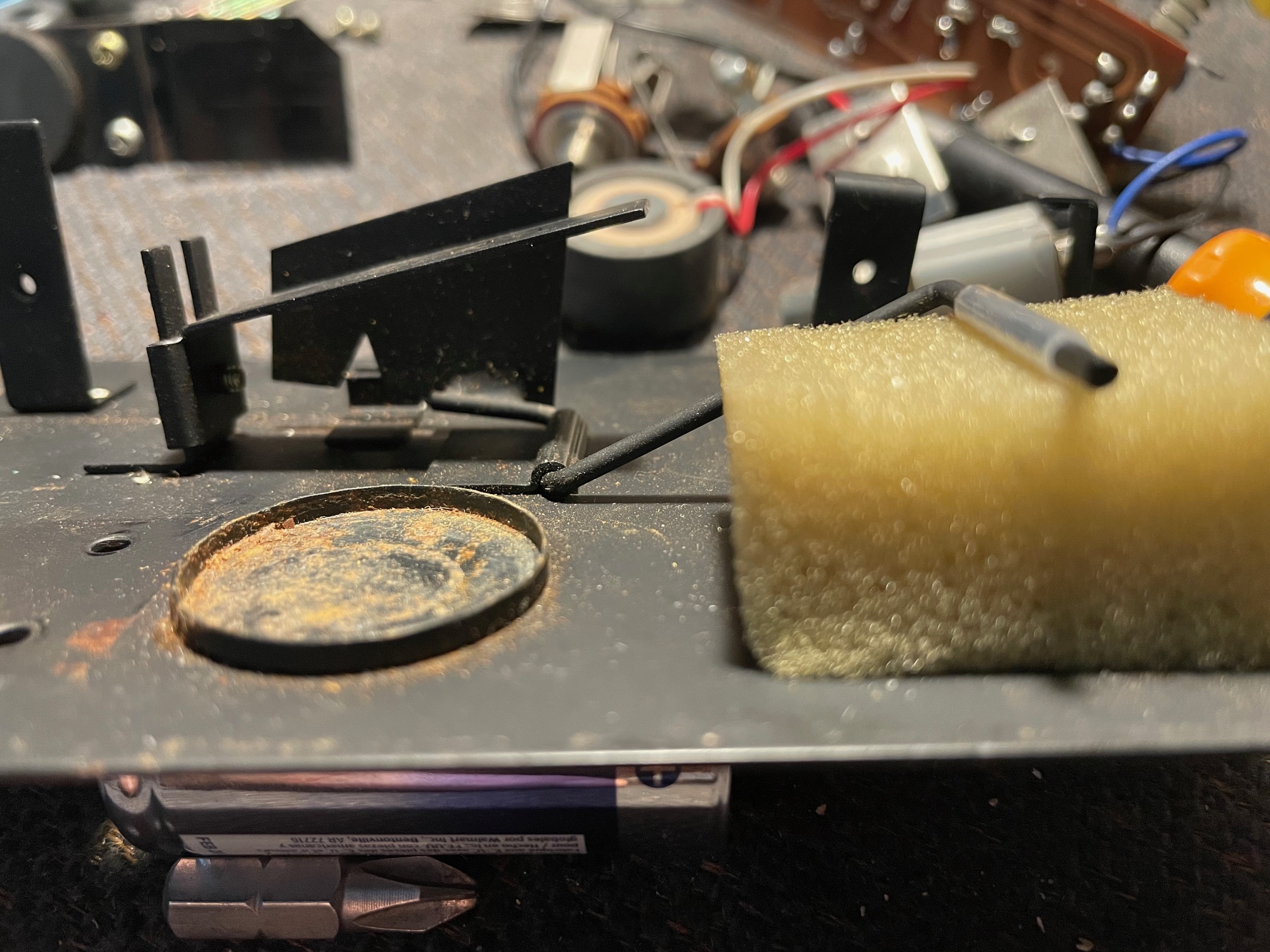 |
When gluing the inductor back onto the baseplate, make sure to clean up any rust, dust, etc. to ensure a good bond. Here you can also see the triangular cutout in that shutter late mentioned earlier. |
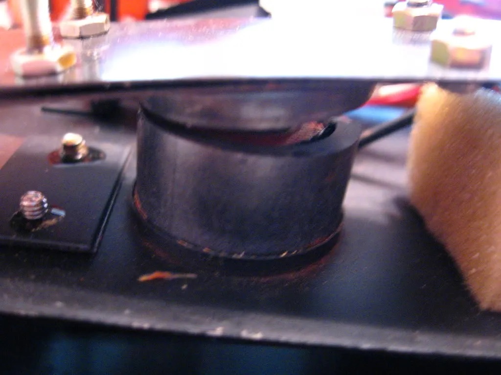 |
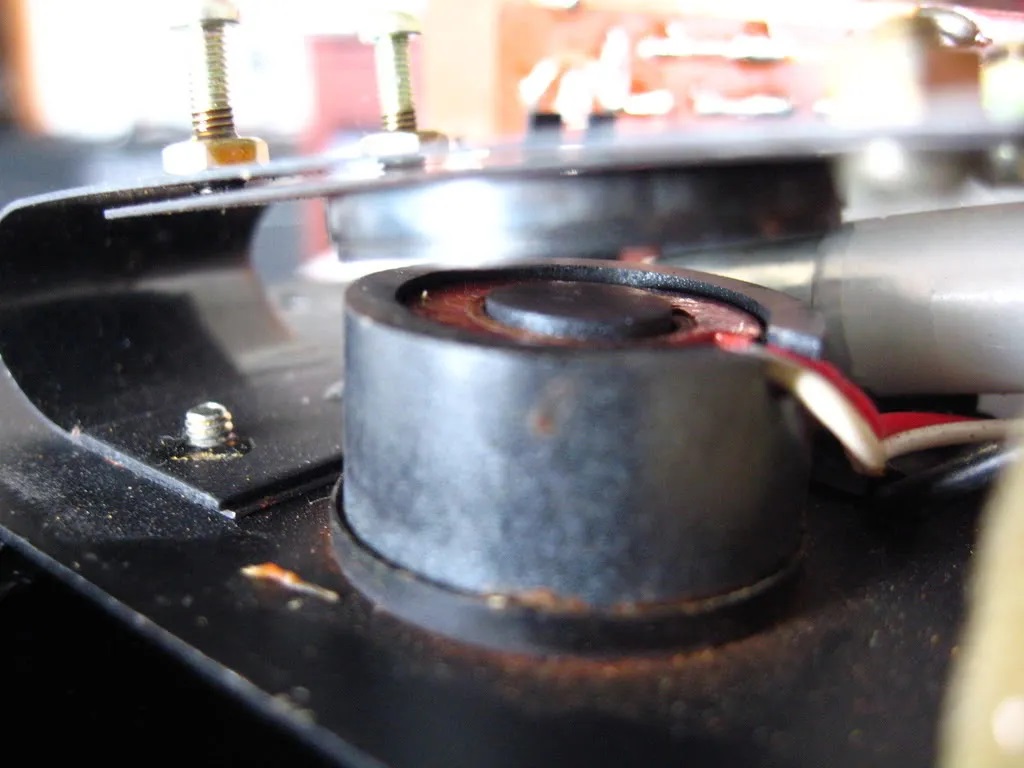
Here is what it looks like with everything reassembled. The wah effect is governed by how close this piece of ferrite on the spring is to the inductor, which has a ferrite core and cup as well. These inductor assemblies are unicorns - there are no replacements so be careful not to break any of those parts! |
 |
The inductor has me a bit confused. The schematic states that it is 2.7 Henries with what I presume is 1400 turns on an unknown gage of wire. When I measured it, it ranged between about 200mH & 500-ish mH. Not sure what the deal is with that but it works good. The ferrite seems to be very slightly magnetic. The inductor cup/core has Gauss strength of approx. 1.08 and the loose ferrite piece is approx. 0.45 and the measured DC resistance was 89 ohms. |
 |
In this picture you can see the coil removed from the ferrite cup. The copper wire is very tiny, something like 48 gage. These were also glued into the cup with a very small amount of glue and these can also come loose over time. |
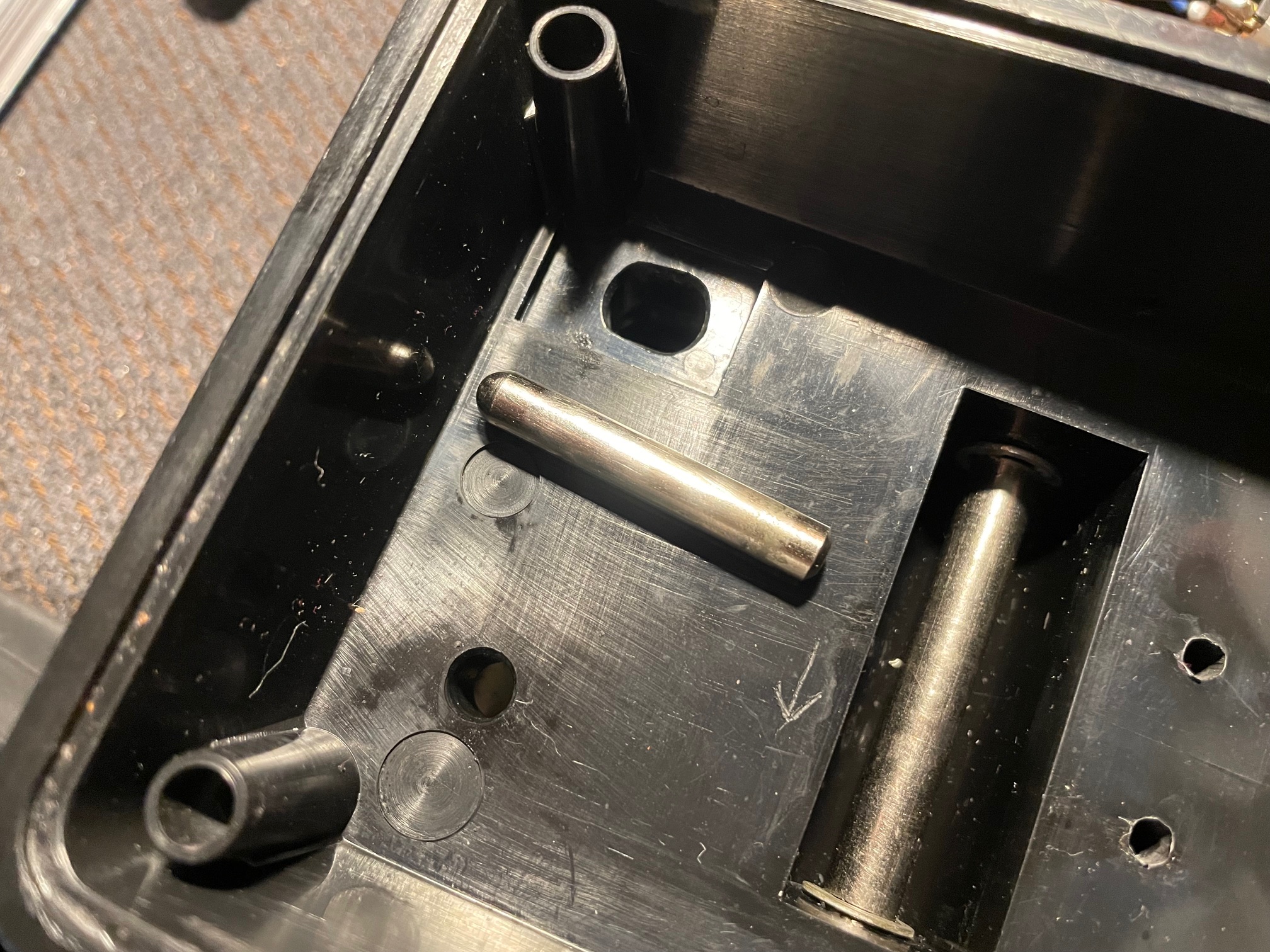 |
One interesting feature of this pedal is the push-rod actuator. This is what presses down the on the end of the flat spring when the heel end of the treadle is pushed down. I cleaned and lubricated it while I was doing my restoration work. |
 |
Here you can see the push-rod actuator as it appears when the pedal is reassembled. |
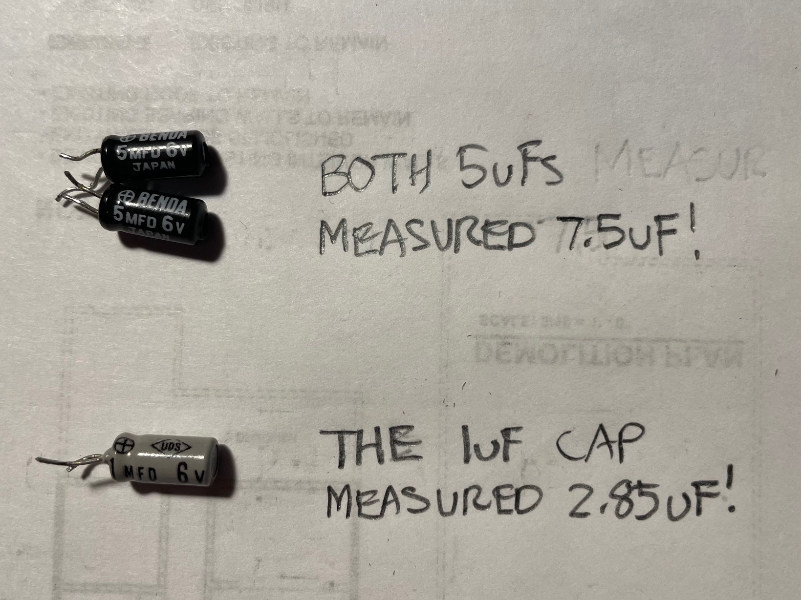 |
After I had reattached the inductor and got all of that working properly it still didn't sound right. The "wah wah" effect was weak. Although it seems uncommon for electrolytic caps to dry out in 9V (or less) circuits, I decided to check the electrolytic capacitors since they were all in important strategic positions in the circuit. Turned out that the 5uf caps measured 7.5uF! The 1uF input cap was high ESR and measured 2.85uF! After those were changed the circuit really came to life again. It was kind of a pain to do as these units are not the easiest things to work on but for me worth the effort. |
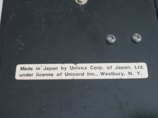 |
Footnote: Some units had this sticker on the bottom. Not sure what the story is on that. |
There was still some more work for me to do on this pedal to get it to 100%. Two of the carbon comp resistors had drifted way out of tolerance so they needed to be replaced,
especially since one of them involved properly biasing one of the transistors. One other thing I had to contend with was the volume function. When in volume mode the output was maybe half as loud as the wah mode. This had me puzzled and I thought it might be an electronic related issue but I eventually noticed that when I had the circuit out the enclosure it would work as expected and when I put it into the enclosure it had very low output. It was then that I realized that the plunger was pushing down on the spring too much when it was in the enclosure. A downward movement of approx. 3/8" on the flat spring will go from full volume to almost none. The solution to this problem turned out to be very simple. All I had to do was to apply a torsional force on that wire to bend it slightly towards the bottom plate, so that when I put it back in the enclosure there is no push back from the flat spring. This way when the circuit block is inserted into the enclosure you get full volume in toe down position. I also confirmed the output levels with an oscilloscope before doing any of this. The outputs between the two modes are close to the same. Interestingly, I noticed that this circuit generates a little bit of asymmetrical distortion, as the tops of the waveforms are a little clipped. I discovered that the circuit produces second order harmonics, which I also found to be very interesting. Anyway, doing this simple modification does not really affect the wah mode at all and it makes the volume function quite usable. It will do Holdsworth-like volume swells quite nicely with very little movement of the treadle. It takes a little getting used to the short travel but with a little practice, in terms of the sweep, it's not that different from any other volume I have used.
Overall I enjoy the unique character of the Uniwah, and to my ears, it is not harsh sounding. It seems that the problems these units can have, which I have outlined on this page, are pretty typical for a lot of the Uniwahs out there as they are around 50 years old now. If you acquire one, be prepared to do a little work on it.
None of it is difficult, but it IS tedious and requires some care to not the damage parts which are irreplaceable unicorns. I know some people like to poo poo the plastic
enclosure but the plastic is quite tough and I'd even go so far as to say it's likely far more durable than any plastics made today. I am impressed with the manufacturing of this thing considering these were made from late 1968 to sometime in the early 1970s, when CAD and 3D programs did not exist. Everything fits together well and the tolerances are pretty tight. Not all the "made in Japan = junk" thing I'd hear when I was a kid!
Silicon Sensors Data Sheet (LDR)