Seymour Duncan Convertible FET Preamp Module
Last updated 11/03/02
This is a seldom seen module. In terms of design, this module is
a rather simple one compared to some of the other ones that were
available. It uses a single ECG312 FET (Field Effect Transistor)
powered off of B+ voltage (360-400VDC) through some voltage
dropping resistors (in series) and a few other resistors for
biasing the FET, etc. and some filtering/decoupling capacitors.
Operating voltage appears to be somewhere between 20 and 24
volts. This module utilizes a Source Self-Bias Circuit. This
particular FET wiring arrangement is more like cathode bias on a
tube where no separate bias voltage is applied, since a fairly
acceptable bias can build up by itself if the correct value
resistors are used in the right place, depending on B+ and the
FET's characteristics. True to Seymour Duncan's literature, it
has tube-like characteristics.
It was a real challenge creating a schematic, component layout
and PCB layout with only these two rather low quality pictures
below. Fortunately, I know a few electronics gurus who helped me
figure out the basics. John G., a regular visitor to the ampage
forum, drew up the schematic for me. And MBSetzer, another
regular visitor of the ampage forum helped me with understanding
the circuit. (Many Thanks!)
I built this module, and it works. I had a few problems getting
it to work properly at first. The FET was improperly biased,
causing signal degradation and premature signal cut-off. I was
apparently misinformed about some of the resistor sizes
controlling the FET bias, or the "equivalent" FET
characteristics are not exactly the same as the original. But,
anyhow, I figured out what was going on by measuring voltages and
adjusting resistor sizes until it worked properly. I'm not 100%
sure this sounds exactly like the original module does, but I
think it's very close. (The verified original FET resistor values
given to me were as follows: Gate - 1M, Source - 3.9K and Drain -
1.2K) After doing a gain calculation on my homegrown module,
based on the FET characteristics, and an estimated B+ current, it
appears that this module can have a gain factor between 60-90,
which will vary depending on the individual FET IDSS & Vfs
characteristics. These numbers can vary quite a lot within the
same device! That makes the gain equivalent to the average 12AX7
preamp tube. Not too bad for a single gain stage FET circuit.
This module adds sustain to lower gain distortion modules, like
the Classic Distortion module, and reduces microphonics as well.
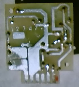
Original module shown below.
Photos contributed by James A. Maggio
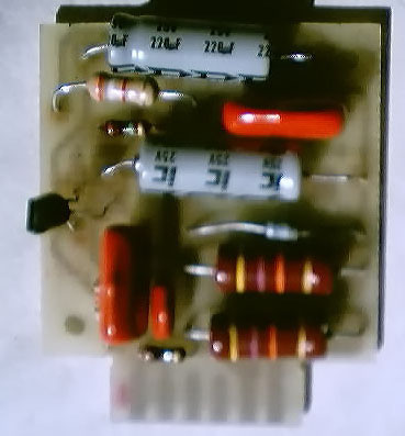 |
 |
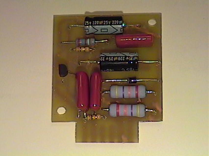
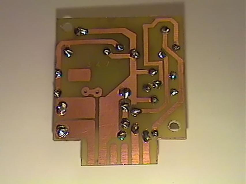
Shown below is the FET module that I manufactured. It took about
two hours to make, from start to finish. That includes etching
the board, cutting it to size, drilling the holes and soldering
all of the components to the PCB. (Not counting the time it took
to debug the circuit)
 |
 |
I built this module mainly just to see if I got everything right,
and of course to see how it sounds. It was very hard to tell what
the components were from the pictures I got, so I wanted to make
sure it actually worked before posting schematics and layouts. It
only cost me $15 to make, buying the parts at the local
electronics supply. That works out to each component being about
$1 a pop, counting buying an extra FET (just in case).
If you have any additional information or corrections to
contribute, please send me an email.