Shaka Tube Clipping Characteristics
By Paul Marossy
Last
Updated 8/30/04
Since my original Shaka Tube pedal (called the "Bulldog") was off of my
pedalboard for a day, it was begging me to check out its curves... It's
really interesting to see these waveforms that you think sound good. A lot
of the time, they don't look anything like you would expect them to.
The scope was my old Tektronix Model 453 with settings as follows:
Volts/Div 0.1V, Time/Div 0.5uS, Slope set to "+". Scope was in chop mode
with no input on B to give a flatline to reference to. 600Hz sine wave at
20dB attenuation was fed into the input. These are what the waveforms look like at the output of the pedal.
The volume control was set at 5:00 for all shots below.
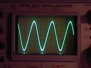
Here is what the waveform looks like with gain at 7:00 and tone at 7:00. Pretty much a clean sine wave, an amplified replica of what comes out of the signal generator.
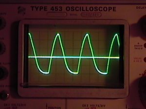
Here it is with gain at 11:00 and tone at 7:00. Bottoms are getting a little squashed.
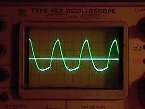
Here it is with gain at 2:00 and tone at 7:00. Bottoms more squashed now.
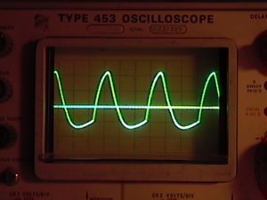
Here it is with gain at 5:00 and tone at 7:00. Not much change to be seen.
Here it is with gain at 5:00 and tone at 11:00. Now the tops are getting
clipped and it looks like the pulse width changes a little bit, too. This is starting to sound harsh to my ears, meaning very "bright".
Here it is with gain at 5:00 and tone at 2:00. Volts/Div switch was set to
0.2V for this shot. This sounds harsher.
Here it is with gain at 5:00 and tone at 5:00. Volts/Div switch was set to
0.2V for this shot also. This to me sounds like the old "ice pick in the
forehead" sound. It also looks kind of jagged. Next, I decided to see what
the waveforms look like right at the gain control since I had a hunch that
the JRC4558D BJT opamp may be clipping the signal hard.
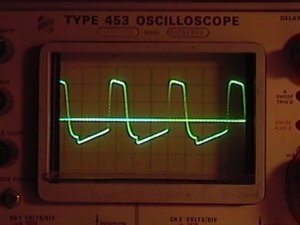
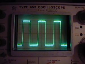
Here is the gain control at 10:00. The bottoms are getting clipped more
than the tops. Pretty hard clipping going here, characteristic of transistor
clipping. This doesn't sound all that bad, though.
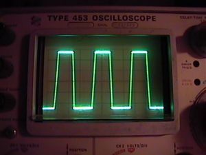
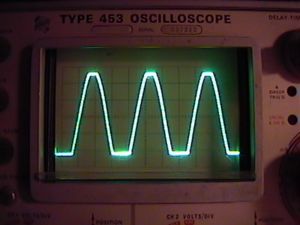
Here is the gain control at 12:00. Looks almost like a square wave. Now,
the amplitude has gotten much larger, and the tops are really clipped,
so much that they are starting to resemble square waves.
This is pretty much how it looks with the gain control between 1:00 and 5:00. Basically, you get really tall square waves. This is some really hard clipping going on with lots of odd order harmonics. The interesting thing here is that, usually, square waves sound very buzzy. But, in the case of the Shaka Tube, it doesn't really sound very buzzy. Perhaps the characteristics of a 12AX7 preamp tube running at such low voltage has something to do with how it sounds in the end?
Next, I compared the clipping characteristics of my original build
with a JFET type opamp installed instead to see if the opamp clips the
signal differently. In my first build using a JRC4558D, with the gain
at max., it's a pretty uniform, symmetrical square wave. There is a TL072
installed in my new build. Looking at the waveform directly at the opamp
output, with the gain at maximum, it is also a square wave, but it is
asymmetrical as far as pulse width goes. At the opamp output, the two
really clip about the same, except that TL072 has some curious little "spikes"
on both corners of the square wave, top and bottom.
On my Shaka Tube in a 1590BB Hammond enclosure, I thought I would compare
that to my first one. The are some slight differences in the parts used
between the two builds. They consist of the following: On my earlier Shaka
Tube build, I used a 390pF cap in parallel with the gain control instead of
the specified 250pF and a 4.7uF cap after the 220 ohm resistor connected to
Pin 2 of the opamp instead of the 2.2uF as specified on the schematic. Also,
I used a 50K pot for the tone control instead of the 100K as specified. On the new build, it is built exactly per the schematic.
Scope used was the Tektronix 453 with a 1M/13pF probe, Time/Div set to 0.5mS
Volt/Div set to 50mV, Input Signal was 600Hz sine wave with 20dB attenuation,
slope set to "+" and chop mode was on with no input on B to give a ground reference line. Here is what I found:
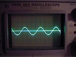
This is with volume at 2:00, Gain at 9:00 and Tone at 12:00. Pretty much a slightly amplified sine wave.
This is with volume at 2:00, Gain at 10:00 and Tone at 12:00. An interesting transformation has taken place here.
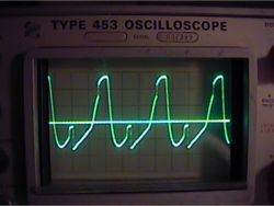
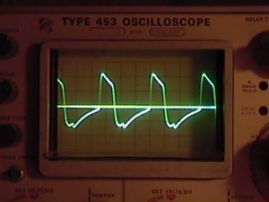
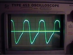
This is with volume at 2:00, Gain at 2:00 and Tone at 12:00. Now there is a curious hump in the middle of the bottom halves. You can see this in the first set of pictures above, too, but these are more pronounced.
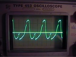
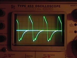
This is with volume at 2:00, Gain at 5:00 and Tone at 12:00. No too much change to be seen here.
In the new 1590BB build, other than a change in amplitude, there wasn't much change with adjustment of the tone control nor did it change much with frequency. The bright switch (0.01 cap to ground on the output) didn't have much effect, either.